MAN0878-09-EN_XLE_XLT_UserManual
A u g u s t 2 3 , 2 0 1 8 P a g e 30 | 158
6.3 Wiring
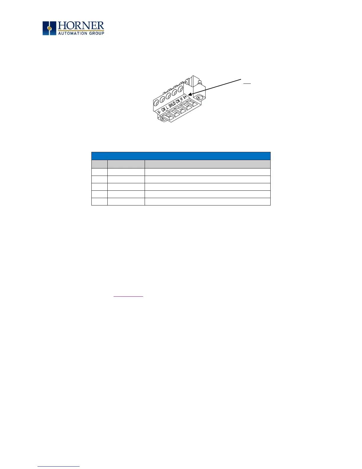
Figure 6.1 and Table 6.1 show how the CAN 1 port pins are assigned.
Figure 6.1 – CAN1 Port Connector
Table 6.1 – CAN 1 Port Pin Assignments
6.4 Cscape Programming via CAN
The CAN 1 port supports CsCAN Programming Protocol. If a PC has a CAN interface installed
(via PCI card or USB), and the PC CAN port is connected to the XLE/XLT CAN 1 port, Cscape can
access the XLE/XLT for programming and monitoring.
In addition, the XLE/XLT supports single-point-programming of all XLE/XLT and other OCS/RCS
devices that are connected to a CAN network. If the PC COM port is connected to the XLE/XLT
programming port (see Chapter 5), the XLE/XLT can act as a pass-through gateway allowing
Cscape to access all XLE/XLT and OCS/RCS devices that are attached to the CAN network.
NOTE: The V+ connection is
not required on the XLE/XLT.
The XLE/XLT network port is
self-powered. Supporting
devices can require this
connection, and this pin can
be used to land the extra wire
required for those devices.
CAN Connector
Use the CAN Connector
when using CsCAN
network.
Torque rating: 4.5 – 7
in-lbs
(0.50 – 0.78 N-m)

 Loading...

