MAN0878-09-EN_XLE_XLT_UserManual
A u g u s t 2 3 , 2 0 1 8 P a g e 26 | 158
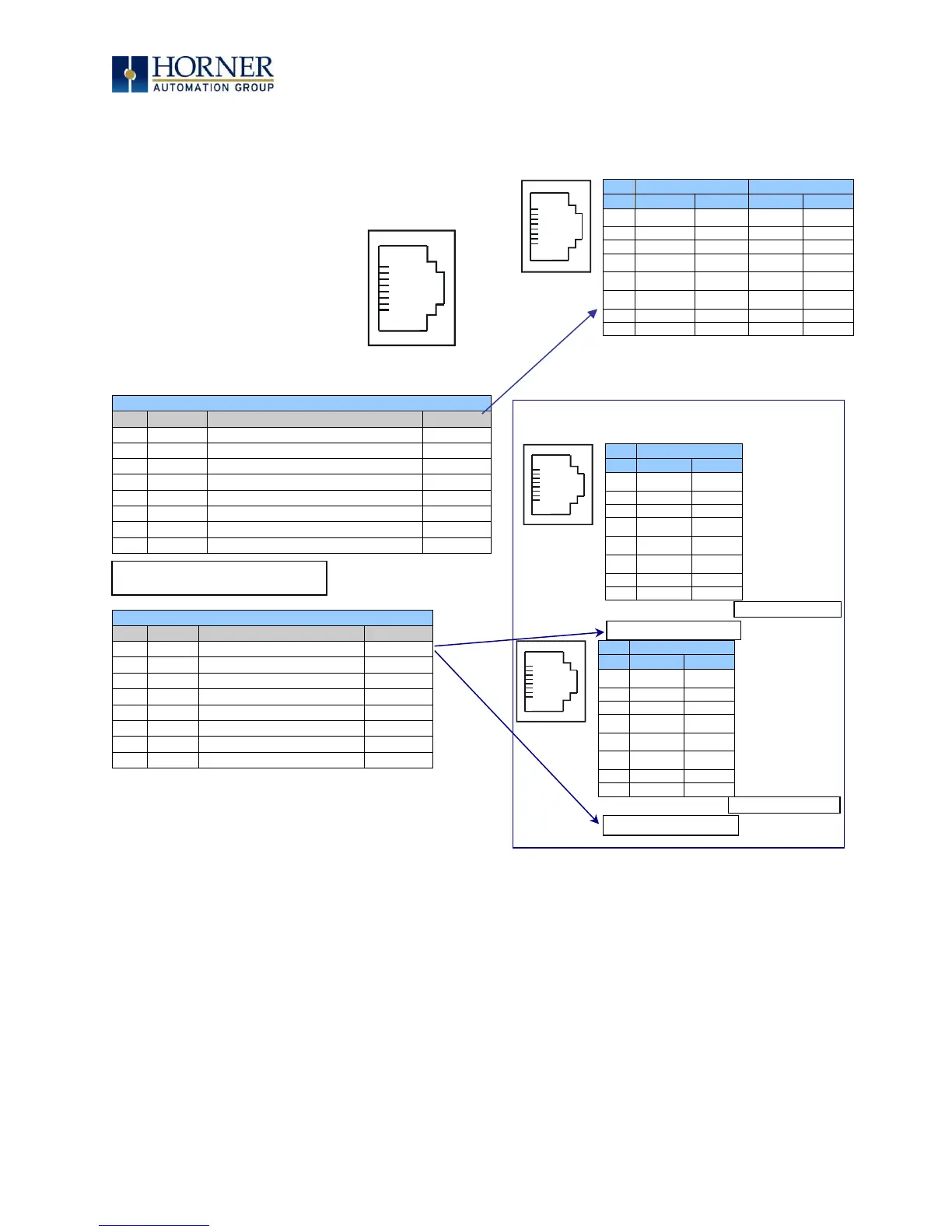
5.3 Wiring
The figures along with Table 5.1 and Table 5.2 show how the MJ1 and MJ2 serial port pins are
assigned.
Figure 5.1 – MJ1 & MJ2 Serial Ports
Table 5.1 – MJ1 Serial Port Pin Assignments
RS-485 Receive/Transmit Positive
RS-485 Receive/Transmit Negative
Table 5.2 – MJ2 Serial Port Pin Assignments
Signals are labeled for connection to a DTE device.
NOTE: MJ1 and MJ2 look the
same but have different pin
assignments and functions.
• * +5 on XLE Rev E and later
• * +5 on all revisions XLT
MJ2 Pinouts in Full and Half Duplex Modes

 Loading...

