EasyManuals Logo

HORNER XLE-Model 2 User Manual

HORNER XLE-Model 2
158 pages
To Next Page IconTo Next Page
To Previous Page IconTo Previous Page
Page #72 background imageLoading...
Page #72 background image
MAN0878-09-EN_XLE_XLT_UserManual
A u g u s t 2 3 , 2 0 1 8 P a g e 72 | 158
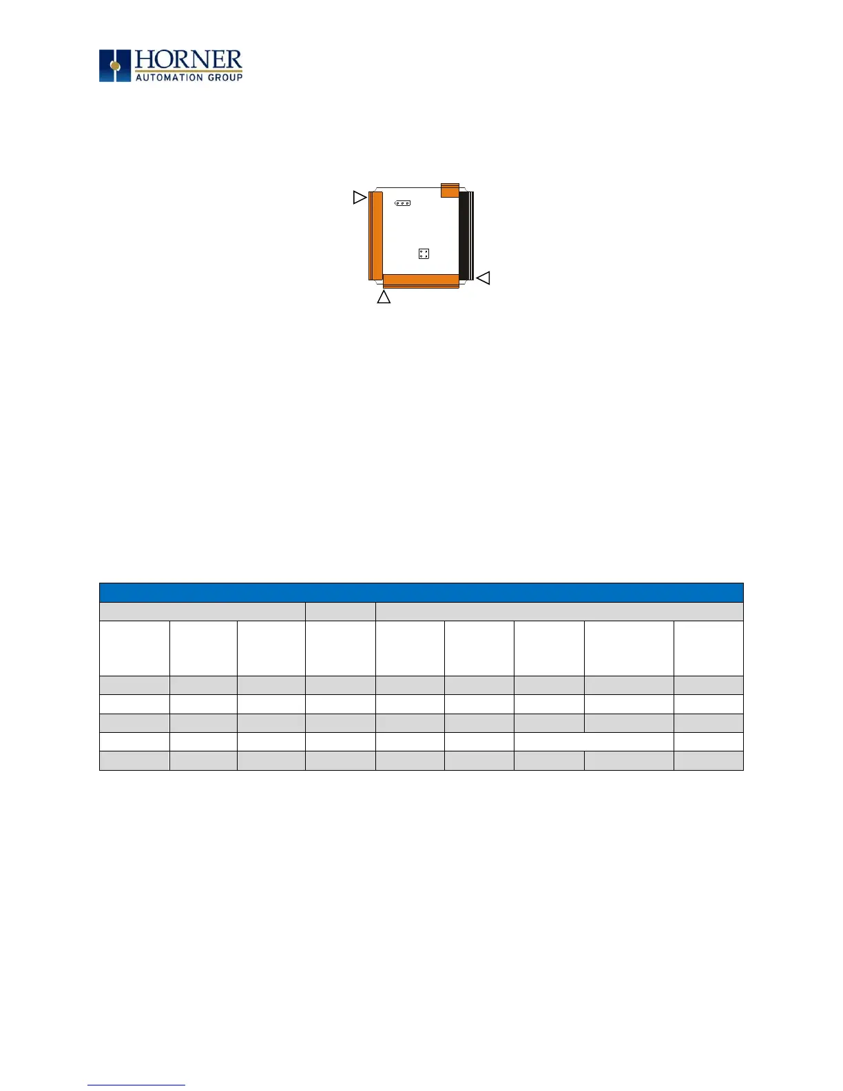
Once the back is removed the jumper selection can be changed. The jumper settings are
documented on each data sheet using a diagram such as Figure 11.2 below and a description of
the jumper settings.
Figure 11.2 Example Jumper & Connector Diagram
To re-install the back cover, place the cover back on the unit. The DIN clip should be on the same
side as the power connector.
Place the screw back into the hole and turn the screw slowly counter clockwise until it clicks
into the threads. This prevents the screw from being cross-threaded. Now turn the screw clock-
wise until the cover is firmly secured. Repeat this process for all four (4) screws. Recommended
torque is 3 - 4 in-lbs (0.34 0.45 Nm).
11.3 Model I/O Overview
Table 11.1 Built-In Digital & Analog I/O
Digital
Analog
DC In
DC Out
(+)
Relay
Out
HSC In*
Pulse
Out**
mA/V
In
mA/V
RTD/TC
(Universal)
mA/V
Out
Model 2
12
--
6
4
--
4
--
--
Model 3
12
12
4
2
2
--
--
Model 4
24
16
--
4
2
2
--
--
Model 5
12
12
--
4
2
2
2
Model 6
12
12
--
4
2
--
6
4
*Shared with total DC inputs
**Shared with total DC outputs
J1 J2
J3
JP3
JP1
001XLE005-R1
J4

Table of Contents

Other manuals for HORNER XLE-Model 2

Questions and Answers:

Question and Answer IconNeed help?

Do you have a question about the HORNER XLE-Model 2 and is the answer not in the manual?

HORNER XLE-Model 2 Specifications

General IconGeneral
BrandHORNER
ModelXLE-Model 2
CategoryController
LanguageEnglish

Related product manuals