(1) PE bar (2) RS485 communication line
terminal (RS485+, RS485–,
GND)
(3) Fan switch (QF1)
(4) Receiver heater/Water
cooling module (QF2)
(5) Fan terminal (6) Temperature control
intelligent monitoring board
The temperature control intelligent monitoring board is located on the inner cover of the
electric control box.
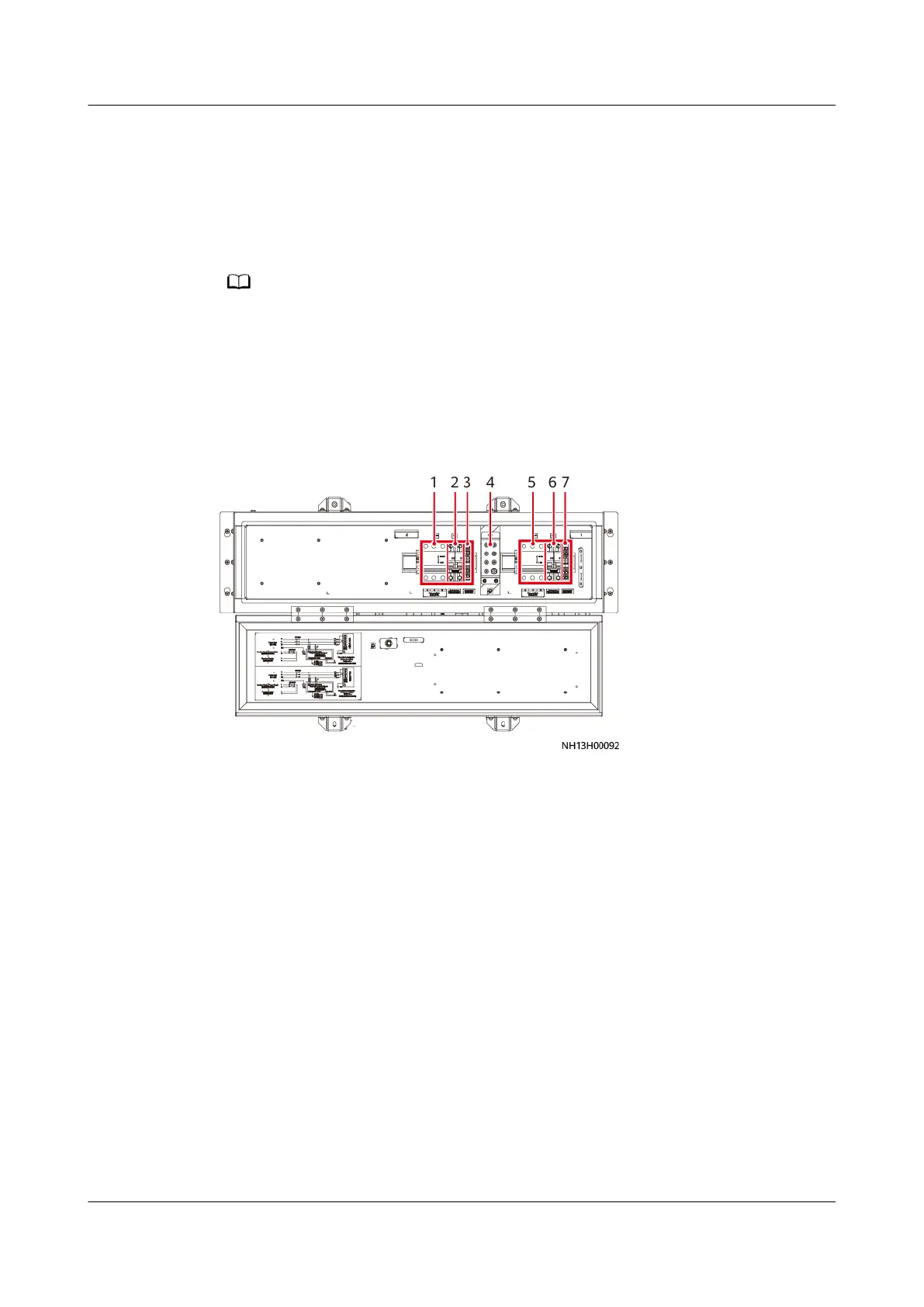
C.4 NetCol500-A120 Electric Control Box Layout
Figure C-7 NetCol500-A120 electric control box (without a temperature control
intelligent monitoring board)
(1) Fan switch (QF3)
(2) Receiver heater/Water cooling module
(QF4)
(3) Fan terminal 2 (4) PE bar
(5) Fan switch (QF1) (6) Receiver heater/Water cooling module
(QF2)
(7) Fan terminal 1
NetCol5000-A050 In-row Air Cooled Smart Cooling
Product
User Manual C Outdoor Unit Electric Control Box Layout
Issue 08 (2021-09-17) Copyright © Huawei Technologies Co., Ltd. 322