WaveLength: 1310nm, Transmission Distance: 10km
Rx Power: -1.43dBm, normal range: [-19.014, -3.000]dBm
Tx Power: -4.86dBm, normal range: [-6.859, -2.857]dBm
Loopback:none, full-duplex mode, negotiation: disable, Pause Flowcontrol:Receive Enable and
Send Enable
Last physical up time : 2012-10-11 10:01:20
Last physical down time : 2012-10-11 10:01:19
Current system time: 2012-10-12 09:53:44
Statistics last cleared:2012-10-12 09:02:03
Last 300 seconds input rate: 0 bits/sec, 0 packets/sec
Last 300 seconds output rate: 0 bits/sec, 0 packets/sec
Input peak rate 88 bits/sec, Record time: 2012-10-12 09:03:45
Output peak rate 78 bits/sec, Record time: 2012-10-12 09:02:54
Input: 2144 bytes, 22 packets
Output: 614 bytes, 7 packets
Input:
Unicast: 21 packets, Multicast: 1 packets
Broadcast: 0 packets, JumboOctets: 0 packets
CRC: 0 packets, Symbol: 0 packets
Overrun: 0 packets, InRangeLength: 0 packets
LongPacket: 0 packets, Jabber: 0 packets, Alignment: 0 packets
Fragment: 0 packets, Undersized Frame: 0 packets
RxPause: 0 packets
Output:
Unicast: 6 packets, Multicast: 1 packets
Broadcast: 0 packets, JumboOctets: 0 packets
Lost: 0 packets,
Overow: 0 packets, Underrun: 0 packets
System: 0 packets, Overruns: 0 packets
TxPause: 0 packets
Last 300 seconds input utility rate: 0.00%
Last 300 seconds output utility rate: 0.00%
3. Record the location of the cables and check whether the labels on the cables
are correct and clear. If the labels are hard to identify, re-make labels and re-
label the cables in case the cables are not connected properly.
4. Wear the ESD gloves or wrist strap and connect the grounding terminal to the
ESD jack on the rack.
5. Pull out the Optical Module to be replaced.
a. Remove the optical cables from the connector and cover the connector
with a dust cap.
b. Pull the bail-clasp or pull-tab latch on the optical module, as shown in
Figure2 and Figure3 respectively.
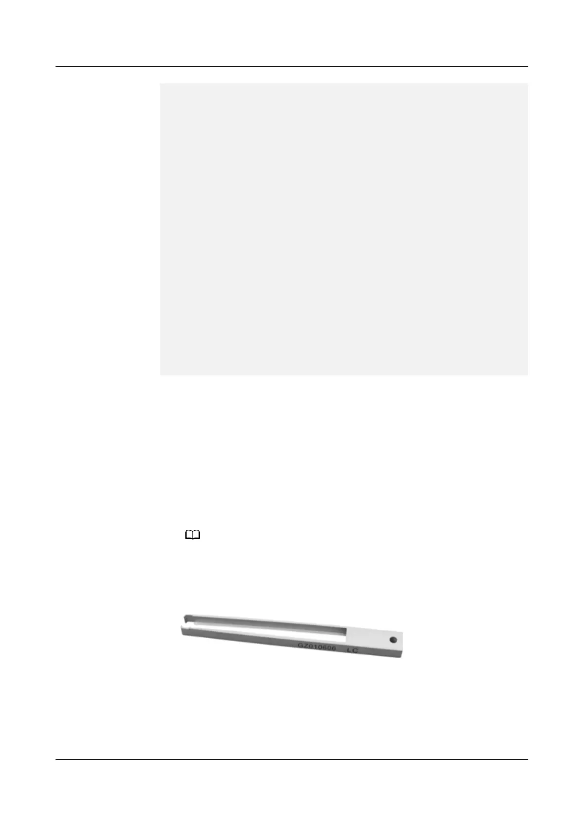
When the operation space is insucient, you can use a ber interface clamp to
remove an Optical Module. Figure1 shows the appearance of a ber interface
clamp.
Figure 4-77 Fiber interface clamp
c. Hold the handle to pull out the Optical Module carefully from the optical
interface, as (2) shown in Figure2. When installing a CFP Optical Module,
hold the screw rods with both hands, and slightly pull out the Optical
Module from the optical port.
HUAWEI NetEngine 8000 F
Hardware Guide 4 Hardware Installation and Parts Replacement
Issue 05 (2023-03-31) Copyright © Huawei Technologies Co., Ltd. 438
 Loading...