According to the national standard (GBT50312-2016), the loss of the optical ber
link connector must meet the requirements described in Table 4-56.
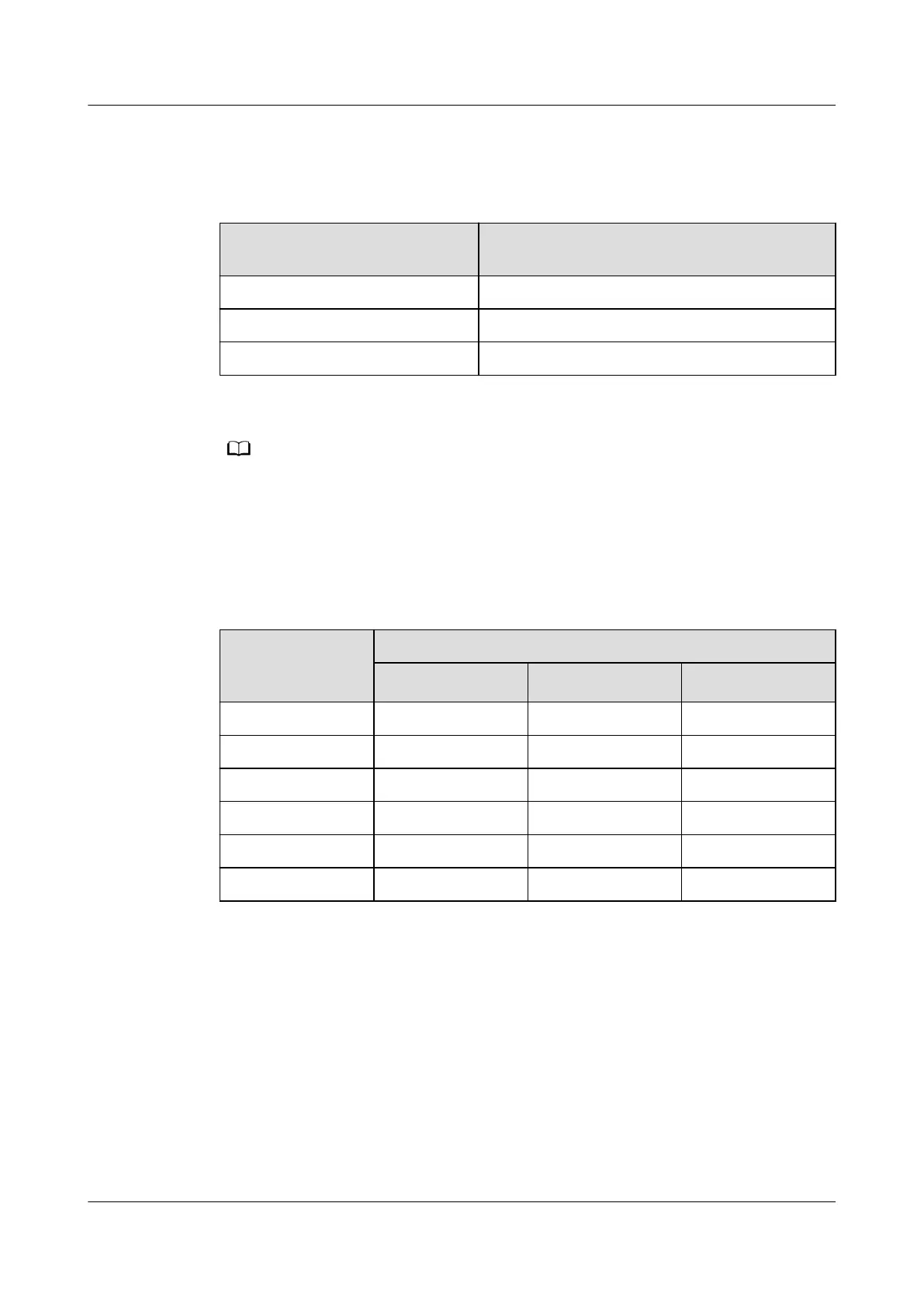
Table 4-56 Maximum attenuation of the optical ber connector
Type Maximum attenuation of an optical ber
connector (dB)
Fiber splicing connector 0.3
Optical mechanical connector 0.3
Optical connector 0.75
Fiber cores are connected through connectors, such as the ODF, optical attenuator, and
ange, in splicing and mechanical modes.
Table 4-57 describes requirements for the reection of the optical ber connector
when Ethernet ports (such as 50G) use PAM4 encoding to double the rate. More
connectors bring lower requirements for the
reection.
Table 4-57 Maximum reection of connectors
Number of
Optical Fiber
Connectors
Maximum Reection of Each Connector (dB)
50GBASE-FR 50GBASE-LR 50GBASE-ER
1 -25 -22 -19
2 -31 -29 -27
4 -35 -33 -32
6 -38 -35 -35
8 -40 -37 -37
10 -41 -39 -39
Procedure
1. After the optical
ber at the peer end is disconnected, use the OTDR meter to
test the local end. Check whether the loss and
reection of each link and
node are normal. (The loss of a ber splicing connector should be less than
0.3 dB, the loss of a connector should be less than 0.75 dB, and the
reection
of a connector should be less than -30 dB.) If the test result is not within the
required range, process the abnormal port.
2. Locate the equipment room where the port resides based on the distance
between abnormal points in the OTDR test result. Preliminarily determine the
port location, disconnect the port, and perform an OTDR test on the port that
HUAWEI NetEngine 8000 F
Hardware Guide 4 Hardware Installation and Parts Replacement
Issue 05 (2023-03-31) Copyright © Huawei Technologies Co., Ltd. 593
 Loading...