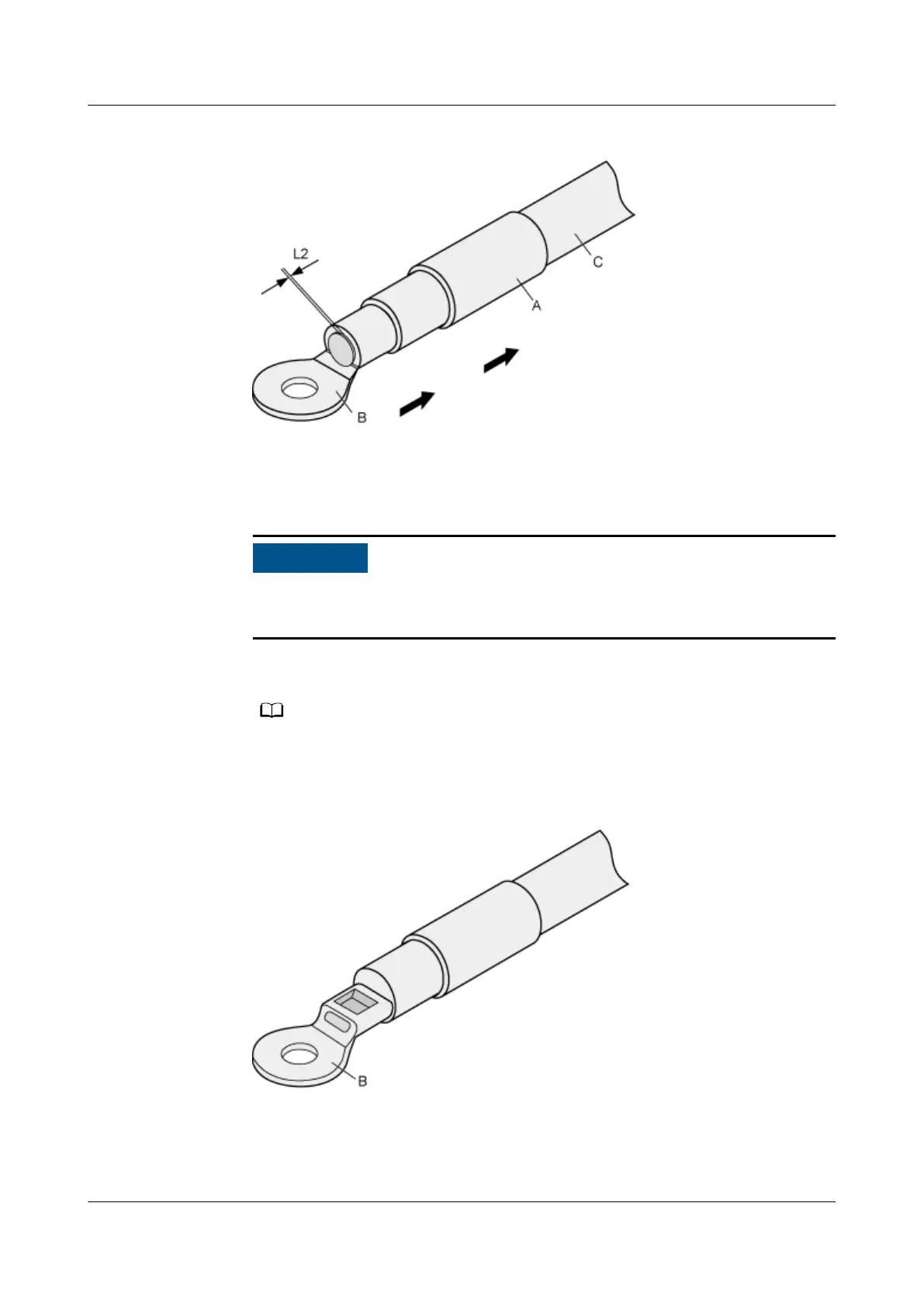
Figure 4-288 Putting the heat shrink tubing onto the bare crimping terminal
3. Put the OT terminal B onto the exposed conductor, and ensure that the OT
terminal is in good contact with the insulation coating C, as shown in Figure
4-288.
After the conductor is fed into the OT terminal, the protruding part of the
conductor, or L2 in Figure 4-288, must not be longer than 2 mm (0.08 in.).
4. Crimp the joint parts of the bare crimping terminal and the conductor, as
shown in Figure 4-289.
The shapes of crimped parts may vary with the crimping dies.
Figure 4-289 Crimping the joint parts of the bare crimping terminal and the
conductor (OT terminal)
5. Push the heat shrink tubing (A) toward the connector until the tube covers
the crimped part, and then use a heat gun to heat the tube, as shown in
Figure 4-290.
HUAWEI NetEngine 8000 F
Hardware Guide 4 Hardware Installation and Parts Replacement
Issue 05 (2023-03-31) Copyright © Huawei Technologies Co., Ltd. 654
 Loading...