Figure 4-333 shows the pins of an RJ45 connector.
Figure 4-333 Pins of an RJ45 connector
Procedure
1. Feed both connectors of the cable into the ports of the cable tester.
2. After the connectors are properly inserted, turn on the tester. If the indicators
from 1 to G turn on simultaneously, you can infer that the pins work normally
and the wires are correctly connected.
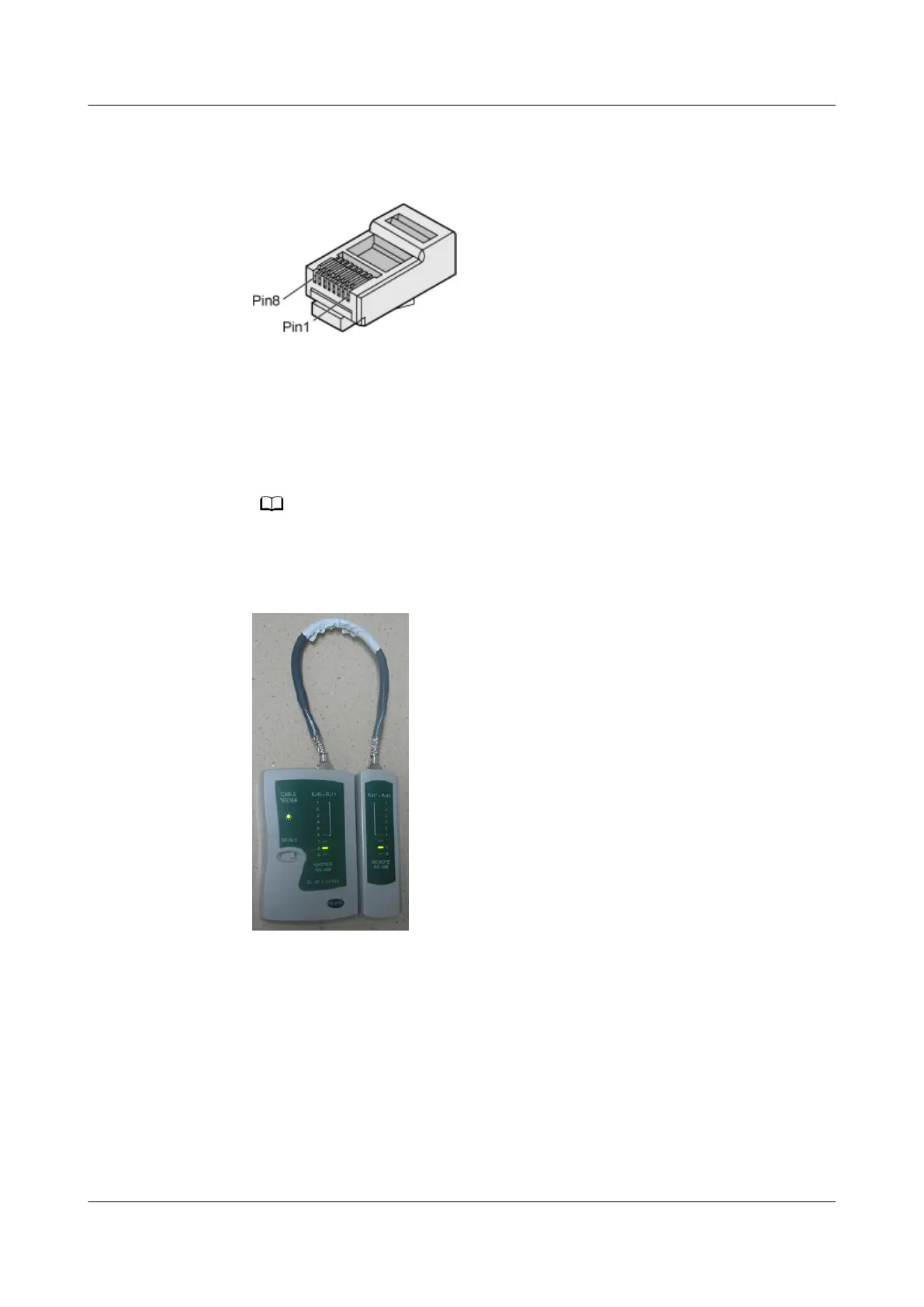
Turn the switch to the S position to slow down lighting of the indicators so that you
can see the indicators more clearly, as shown in Figure 4-334.
Figure 4-334 Testing the conduction and connections of wires
3. Gently shake the connector and repeat Step 2 to check whether the metal
contact strips are in good contact with the core wires and Ethernet ports, as
shown in Figure 4-335.
HUAWEI NetEngine 8000 F
Hardware Guide 4 Hardware Installation and Parts Replacement
Issue 05 (2023-03-31) Copyright © Huawei Technologies Co., Ltd. 680
 Loading...