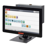
v 1.0 — February 2020 Altanium Matrix5
116 Heats Setup - Monitoring
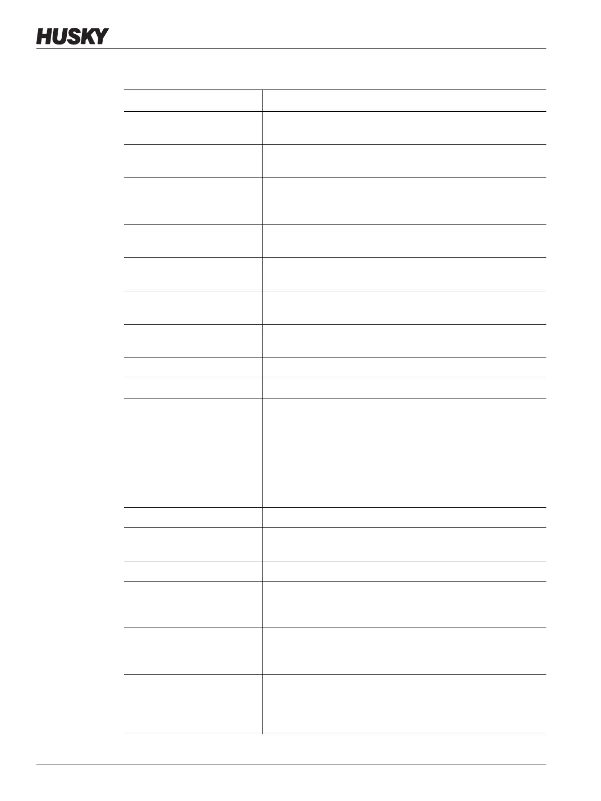
Table 10-5 System Setup Screen - Heats Setup - Monitoring
Item Description
Alarm Sensitivity The duration of time the system has to stay in an error condition
before an alarm occurs.
Maximum Temperature Limit The number of degrees over the setpoint that the Maximum
Temperature Alarm occurs.
No Response Limit A global setting that calculates how long the system should apply
96% power or greater without a 5 degree increase in temperature
before an alarm occurs.
Allow Monitor Regulation for
Selection
Enables the parameter that lets the system change the regulation
mode to “Monitor” for zones in the Quick Set screen.
Exclude Monitor Zones from
At-Temperature
Enables the parameter that lets the system exclude zones that are
set to “Monitor” regulation from the “At Temperature” condition.
Wattage Voltage Insert the designed voltage rating of the heaters so the system can
accurately calculate Watt Voltage.
Supply Configuration Used to select the supply configuration parameter: Delta 3PH,
Wye 3PH+N, Single Phase, or Integrated TX.
Global Output Power Limit Used to control the maximum output power applied to each zone.
Earth Leakage Fault Enable Enable or disable the earth leakage check.
Earth Leakage Limit For ICC
2
cards, a percentage used to calculate the earth leakage
limit when the diagnostic process for a zone is complete. The
control card uses a percentage of the current measured during
the test to make the decision when an earth leakage error occurs.
The parameter range is 0 to 100%. The default value is 10%.
For ICC
3
cards, the value is displayed in milliamps and has an
adjustable range from 1 to 999 mA. The default value is 500 mA.
Display Earth Leakage Reading When ICC
3
cards are installed, this shows the earth leakage.
Circuit Overload Enable Enables or disables the circuit overload error. This shows only if
ICC
3
cards are installed.
Circuit Test Enable Enables or disables the circuit test for ICC
3
cards.
Auto Power Limiting Enable When enabled, the controller automatically adjusts the output
power limit values on zones that have oversized heaters attached.
This setting is disabled by default.
Circuit Test State 4 Power
Level
This is the power level that is applied during pre-state 4 when the
control card calculates the current during circuit test. The range is
from 20% to 50% and the default value is 50%.
Display Causes and Solutions
Enable
When enabled, the controller stops the system and alerts the user
that failures were detected during circuit test. The controller
shows a dialog window of possible causes and solutions data.
Refer to Section 15.8.