v 1.0 — February 2020 Altanium Matrix5
184 Cable Connections
• Safety Signal
• Temperature Control
With each signal type, there can be related signal sources, conditions, and values that must
be set. Configure these as necessary.
13.2 Cable Connections
All cables are connected to the bottom of the Matrix5 MCU, with the exception of the USB
connections on the front of the MCU. The USB connections are used for importing and
exporting data.
The insulation level of control cables and devices connected to Matrix5 I/O’s are as follows:
• 500 V when the devices are powered by a 400 VAC or 415 VAC system;
• 300 V when the devices are powered by a system up to 240 VAC.
NOTE: When the 12 V provided on Input, Part Count, or Remote Load connectors is
connected to external devices, the total current used by all external devices shall not
exceed 1 A.
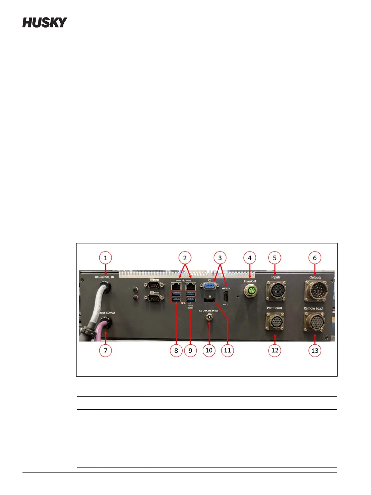
Figure 13-3 shows the Matrix5 connector locations. The connectors are described in
Table 13-6.
Figure 13-3 Matrix5 Connectors, Typical
Table 13-6 Matrix5 Connector Identification
Item Cable Connection Description
1 100-240 VAC In Main AC power from the Altanium mainframe.
2 Ethernet
Interface to customer networks.
3 HDMI or VGA Video signal to touch monitor.
NOTE: Some systems with motion (servo) control will utilize the VGA
connector.