21
[Tool Coordinate System]
It is 128 types of the 3-dimensional orthogonal coordinates + rotation axis coordinate defined
by the tool (such as hand) dimension (offset) attached to the tool attachment surface. Work
coordinate system No. 0 is reserved as offset 0 of tool coordinates by the system.
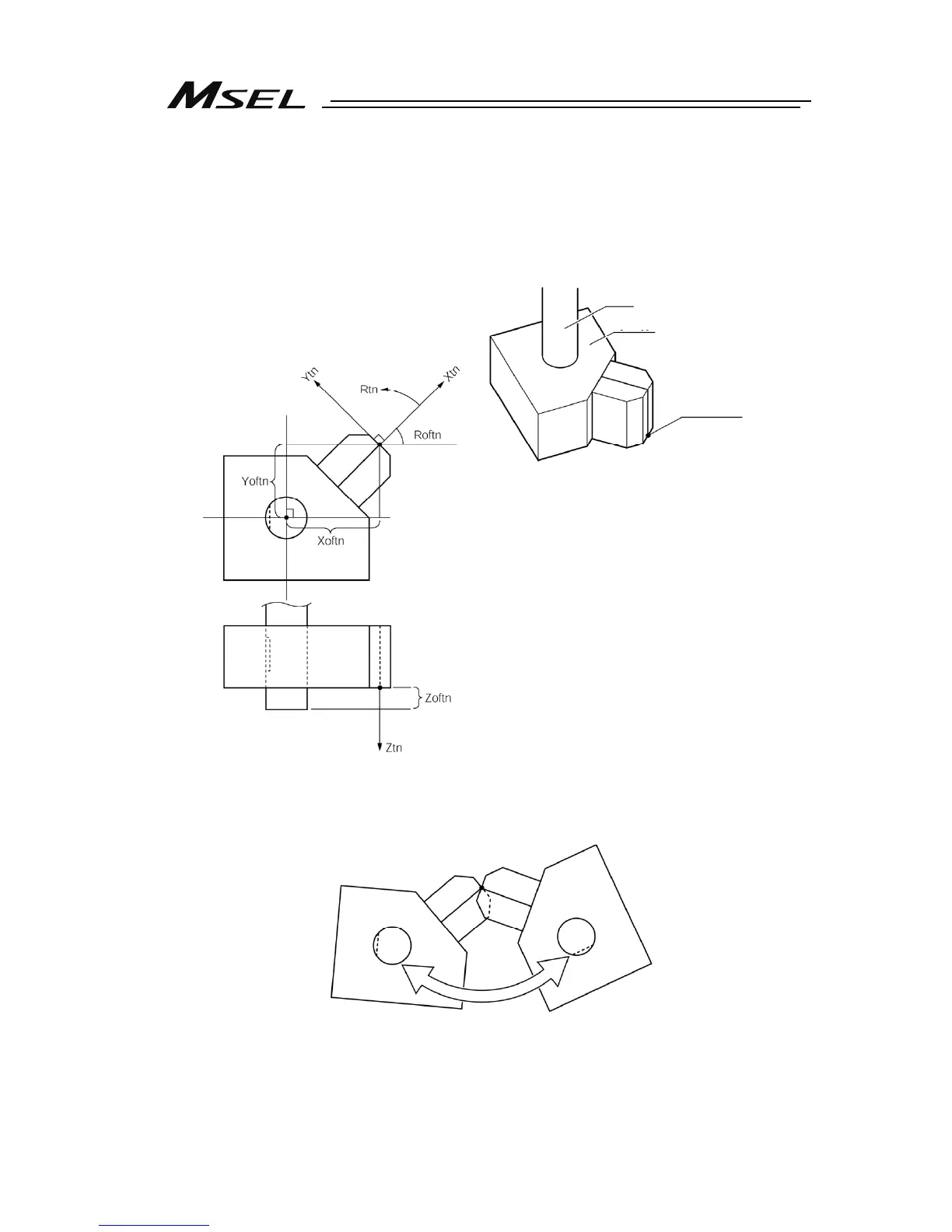
If the defined tool coordinate system number is selected, the tool tip is used as the reach point
at the positioning, not the center of the tool attachment surface.
Select the defined tool coordinate system and operate the R axis with JOG operation, and
such movement as shown in the figure below can be performed.
Xoftn : X Tool coordinate system offset
Yoftn : Y Tool coordinate system offset
Zoftn : Z Tool coordinate system offset
Roftn : R Tool coordinate system offset
Xtn : Tool coordinate system X axis
Ytn : Tool coordinate system Y axis
Ztn : Tool coordinate system Z axis
Rtn : Tool coordinate system R axis
(n is the toof coordinate system number)
Tool
R-axis
Tool ti

 Loading...


