25
4.2.3 Wiring the Power Supply/Motor Power Cutoff Relay
(1) Wiring the power supply
To connect multiple controllers, provide a relay terminal block.
Use a power cable satisfying the following specifications:
Item Specification
Applicable wire length
Single wire: φ1.0 / Stranded: 0.8 mm
2
, AWG size 18
Stripped wire length 10 mm
* Use a flathead screwdriver with a blade tip of approx. 2.6 mm to push in the wire.
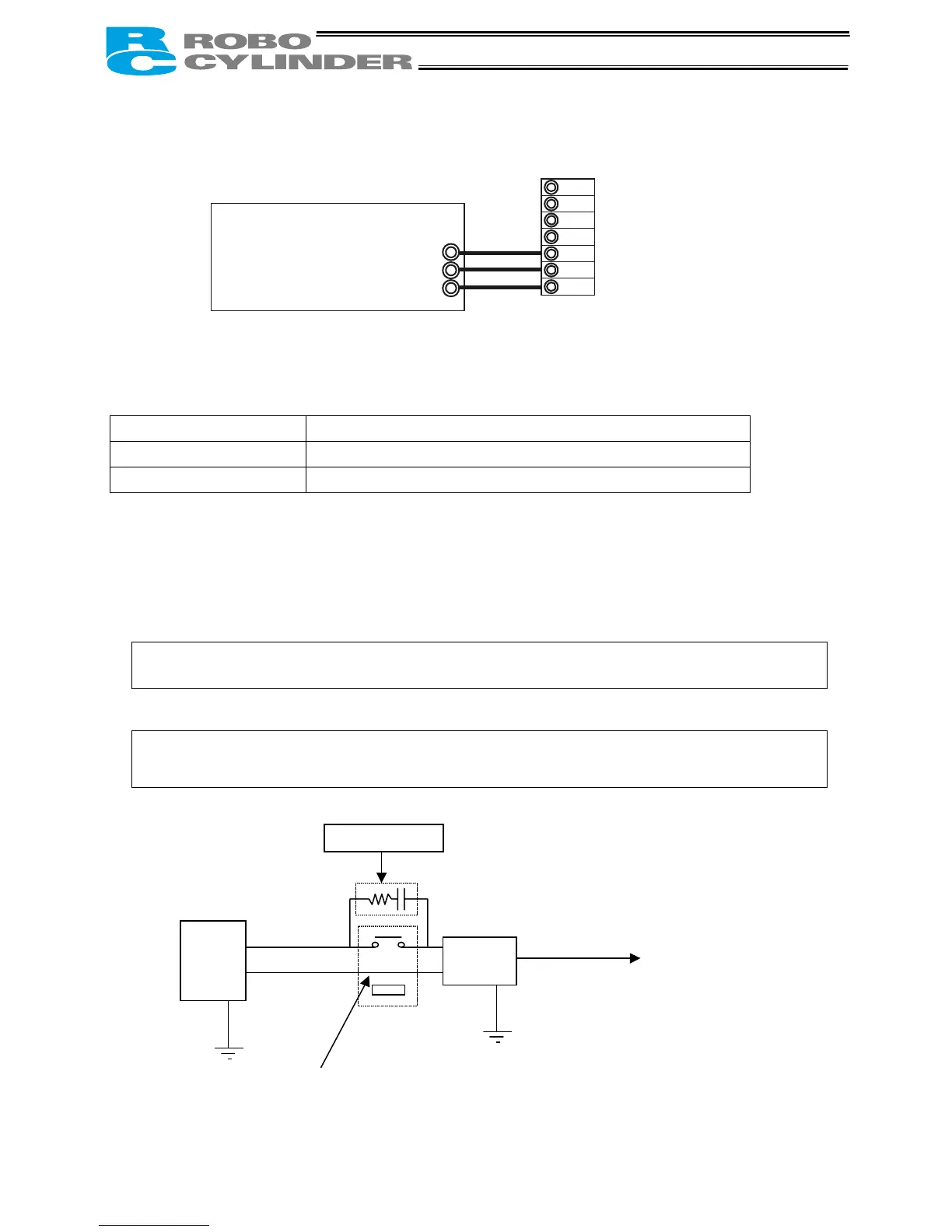
z Notes on wiring the absolute-specification controller
(a) When connecting a relay to the 24-V line, be sure to install it on the positive side of the 24-V power
supply.
Keep the negative side of the 24-V power supply connected without cutting it off with a relay. If a
relay is installed on both the positive and negative sides, an ABS error may generate.
(b) Connect a surge killer to the relay contact.
Chattering of the relay may have negative effect on the controller.
Connect a surge killer to prevent malfunction.
Recommended product: Spark Killer by Okaya
Electric Industries
Model: CR-50500
Capacitance: 0.5 µF ± 20%
Resistance: 50 (1/2W) ± 30%
24V
0V
FG
S1
S2
MPI
MPO
24V
N
FG
Input power supply
24 VDC
(2 A max. per controller)
Surge killer
Relay
Do not install a relay on the negative side.
RCP-
ABS
24V+
24V-
24VPS
AC

 Loading...


