29
z PIO pattern 2 [64-point positioning]
Note: The factory-set PIO pattern is [Conventional], so change the value in user parameter No. 25 to
“2.”
The pause signal may be disabled using user parameter No. 15.
Note: When performing a continuity check of the flat cable, pay due attention not to expand the
female pins in the connector. It may cause contact failure and disable normal operation of the
controller.
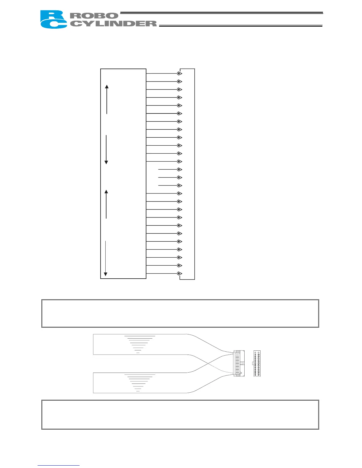
1A P24
2A N
3A PC1
4A PC2
5A PC4
6A PC8
7A PC16
8A PC32
9A CSTR
10A HOME
11A *STP
12A RES
13A
1B
2B
3B PM1
4B PM2
5B PM4
6B PM8
7B PM16
8B PM32
9B PEND
10B HEND
11B *EMGS Available on “RCP2-C.” Not used on “RCP2-CG.”
12B MOVE
13B *ALM
13A 13B
1A
1B
Brown 1
Red 1
Orange 1
Yellow 1
Green 1
Blue 1
Purple 1
Gray 1
White 1
Black 1
Brown 2
Red 2
Orange 2
Yellow 2
Green 2
Blue 2
Purple 2
Gray 2
White 2
Black 2
Brown 3
Red 3
Orange 3
Yellow 3
Green 3
Blue 3
Controller end
PIO (signal abbreviation)
Output side
+24 [V]
0 [V]
Command position 1
Command position 2
Command position 4
Command position 8
Command position 16
Command position 32
Start
Home return
Pause
Reset
Completed position 1
Completed position 2
Completed position 4
Completed position 8
Completed position 16
Completed position 32
Position complete
Home return
completion
Emergency stop
Moving
Alarm
Input side
Upper
stage
Lower
stage
(Note) *STP, *ALM and *EMGS are based on the negative logic.
Host system <PLC> end
Lower stage
Upper stage

 Loading...


