32
4.4 Connecting the Actuator
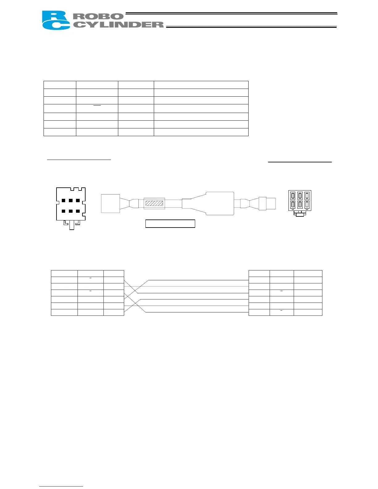
• Connect the motor relay cable to the MOT connector.
Signal table for the controller-end connector (CN2)
Pin No. Signal Wire color Description
A1 A Blue Motor drive line (phase –A)
A2 VMM Black Motor power line
A3
B
White Motor drive line (phase –B)
B1 A Red Motor drive line (phase +A)
B2 VMM Black Motor power line
B3 B Green Motor drive line (phase +B)
Housing: 1-1318119-3 (AMP) Housing: SLP-06V (J.S.T. Mfg.)
Receptacle contact: 1318107-1 Socket contact: BSF-21T-P1.4
4
1
6
3
2
1 3
B
CN2
CN1
CB-RCP2-MA * * *
Blue
Black
White
Red
Black
Green (yellow 3)
VMM
B
VMM
B
1
2
3
B1
B2
B3
VMM
B
VMM
B
1
2
3
4
5
6
Red
Black
Blue
Green (yellow 3)
Black
White
Controller end
CN2 pin assignments
Actuator end
CN1 pin assignments
CN2
CN1
Cable color Signal name Pin name
Pin name Signal name Cable color

 Loading...


