92
9. Controlling Multiple Controllers via Serial Communication
This section explains the connection method to be used when multiple controllers are controlled using the
PC or PLC’s communication module as the host.
9.1 Basic Specifications
Specification item Description
Maximum number of units that can be
connected
16 units
Maximum cable length 100 m or less
Terminal resistor
220 Ω
Provide a communication path via bus connection and be sure to provide a terminal resistor at the end.
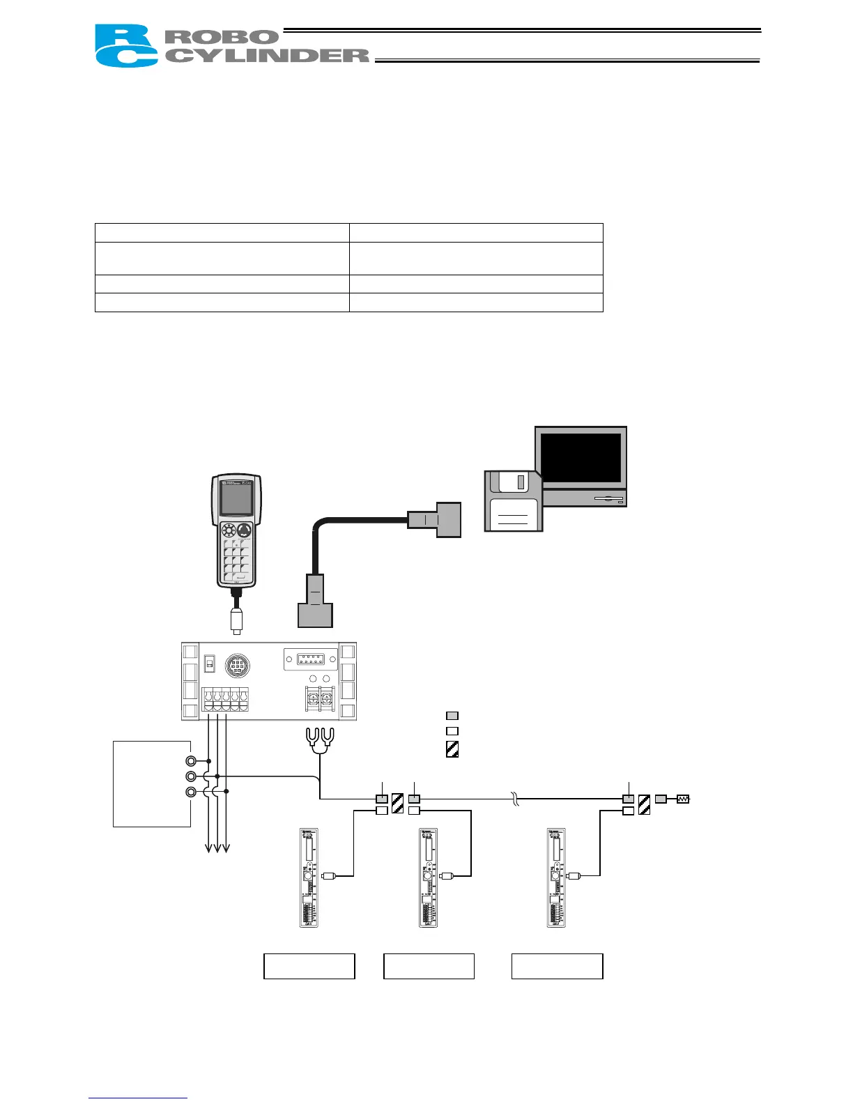
9.2 Connection Example
PC, etc.
Teaching pendant
<RCA-T/TD>
Optional
Cable length: 5
PC software
<RCB-101-MW>
Optional
RS232C cross cable
(Provided by the user)
Components:
SIO converter (with built-in terminal resistor)
<RCB-TU-SIO-A> Vertical type
<RCB-TU-SIO-B> Horizontal type
FG
0V
24V
Input power
supply
Controller power
supply
Terminal resistor
R = 220 Ω
Controller link cable
<CB-RCB-CTL002>
ADRS switch: 0
Controller 1
ADRS switch: 1
Controller 2
ADRS switch: n-1
Controller n
E-Con connector (AMP 4-1473562-4: housing color green)
E-Con connector (AMP 3-1473562-4: housing color orange)
Junction (AMP 5-1473574-4)
Green Green Green
(Note) External equipment communication
cable <CB-RCA-SIO-***> cannot be
used for connection to a PC, PLC, etc.
PERSONAL
COMPUTER

 Loading...


