61
7.1.2 Absolute Specification
(1) Connect the motor cable and encoder cable to the controller.
(2) Connect the host PLC to the PIO connector using the supplied flat cable.
(3) If two or more axes are connected, set the address of each axis using the address switch. For details,
refer to 9, “Controlling Multiple Controllers via Serial Communication.”
(4) Actuate an emergency stop or cut off the motor drive power.
(5) Connect the battery connector.
(6) Supply 24 VDC to the controller’s terminal block.
+ The alarm output signal (*ALM) will turn OFF, the alarm code output signals (PM8 to PM1) will
indicate “1101,” and the ALM lamp will illuminate.
The message “Absolute encoder error (2)” will be displayed on the PC/teaching pendant, if
connected.
(7) Connect a PC or teaching pendant and set the following parameters as the minimum initial settings:
• Parameter No. 15, “Pause input disable selection”
• Parameter No. 21, “Servo ON input disable selection”
• Parameter No. 25, “PIO pattern selection”
For details, refer to 8, “Parameters.”
(8) Reset the alarm.
z Issuing a command from the PLC
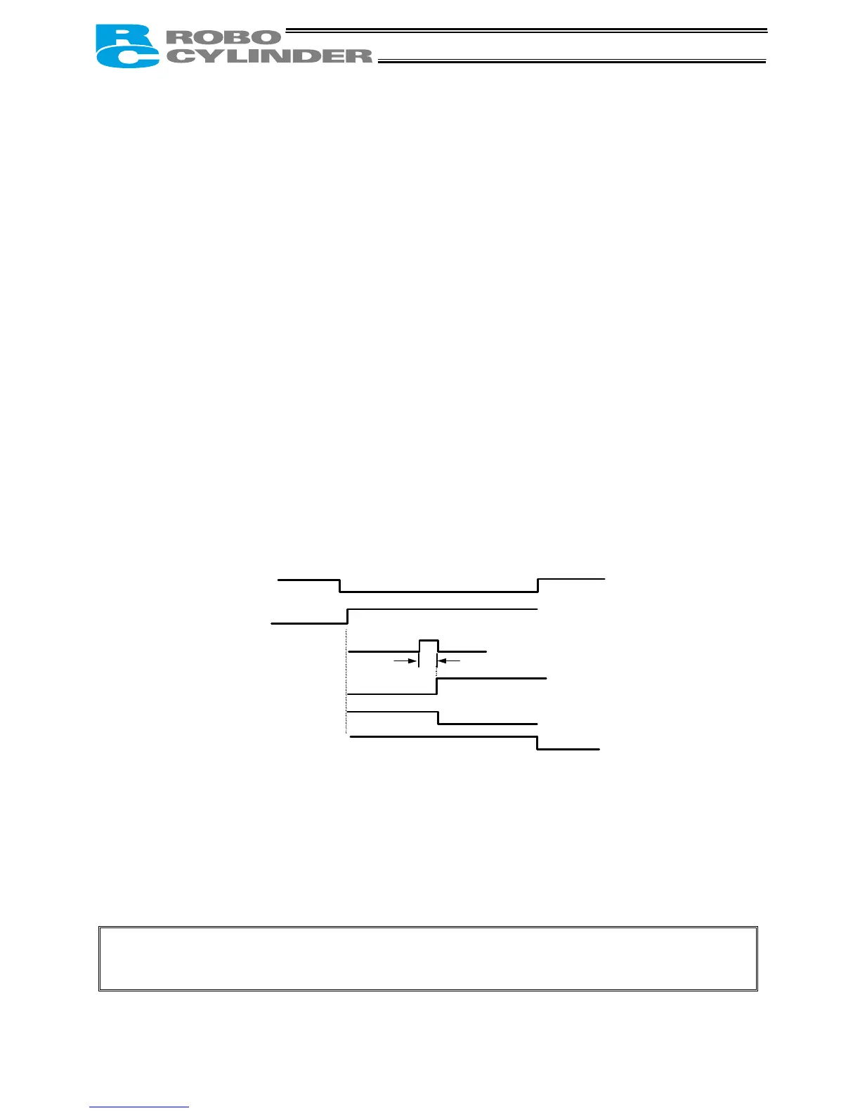
If the PIO pattern is “0: [Conventional],” input the start signal (CSTR) for at least 6 msec.
If the PIO pattern is other than “0: [Conventional],” input the reset signal (RES) for at least 6 msec.
z To reset the alarm from the PC or teaching pendant, refer to the operation manual for the PC or
teaching pendant.
(9) Cancel the emergency stop or connect the motor drive power.
+ The alarm output signal (*ALM) will turn ON, all alarm code output signals (PM8 to PM1) will turn
OFF, and the ALM lamp will turn off.
(10) Turn on the *pause and servo ON inputs at the PIO connector (if the signals are enabled).
(11) The controller is working properly if the RDY and RUN lamps (LEDs) on the controller are lit. If the
ALM lamp (LED) is lit, there is an error. Refer to the alarm table and take an appropriate action.
Note: The batteries are charged automatically while the power is supplied to the controller, so keep
the main power on for at least 48 hours.
Emergency stop
Motor driver power cutof
24-VDC power inpu
Start signal (CSTR)
Reset signal (RES)
Alarm output (*ALM)
Alarm code outpu
(PM8 to PM1)
ALM lamp
Emergency output is actuated
or motor power is cut off.
6 msec or more

 Loading...


