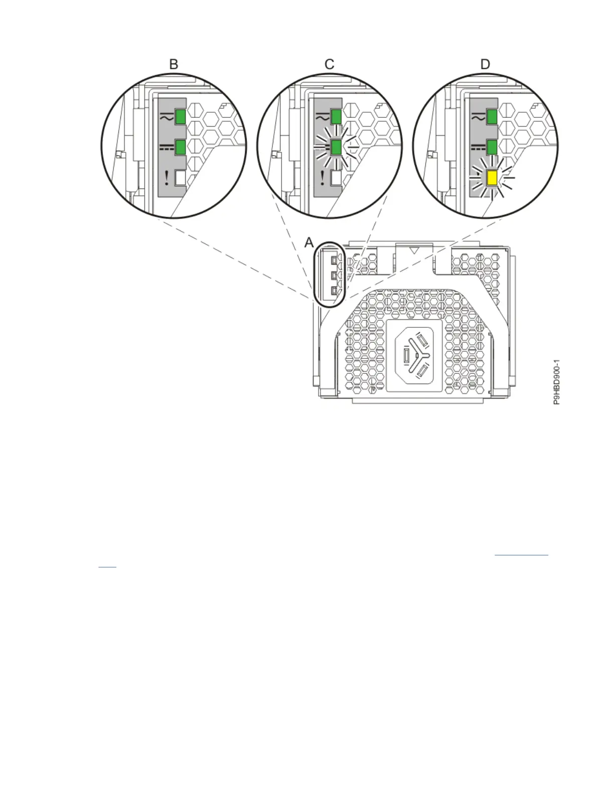
Figure 442. LEDs for a power supply
4. Determine whether you can continue with the system repair operation when the system is powered
on.
To continue the system repair operation when the system is powered on, the following conditions
must be true:
• All 4 power supplies must be installed.
• If only one amber fault LED is turned on, the replace operation can be completed when the system is
powered on.
5. Ensure that the amber LED corresponds to the location of the power supply and the lit fault LED.
6. If you can complete the procedure with the system power turned on, continue with step “8” on page
509.
7. If you need to power off the server to complete the repair operation, complete the following steps:
a) Label and disconnect both UPIC cables from the system control unit as shown in the following
gure.
UPIC cable locations are P1-C1-T1 and P1-C2-T1.
1) Remove the white plastic lock (A) from the plug housing.
508
Power Systems: Removing and replacing parts in the 9080-M9S system

 Loading...