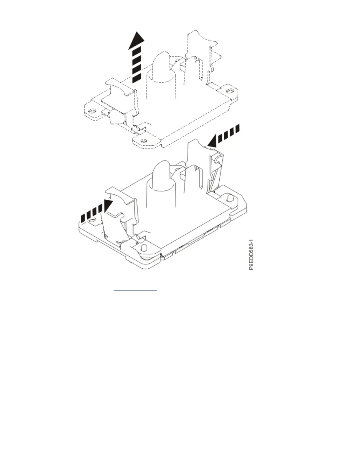
Figure 535. Removing the socket dust covers
c) Continue to step “7” on page 613 to install a system processor module in the socket from which
you just removed the dust cover.
7. Install a system processor module from the original system backplane in the exposed socket on the
new system backplane.
a) Lower the tool over the system processor module on the top cover of the packaging as shown in
the following gure. Ensure that the beveled edge on the tool aligns with the beveled edge of the
processor. Ensure that the two guide pins (A) are inserted into the alignment holes (B) on each
side of the tool.
System backplanes
613

 Loading...