The following table shows the UDIMM memory population rule to optimize the
system performance.
Table 5. UDIMM population rule
DIMM connector 1 DIMM connector 2 DIMM connector 3 DIMM connector 4
Populated Empty Empty Empty
Populated Empty Populated Empty
Populated Populated Populated Populated
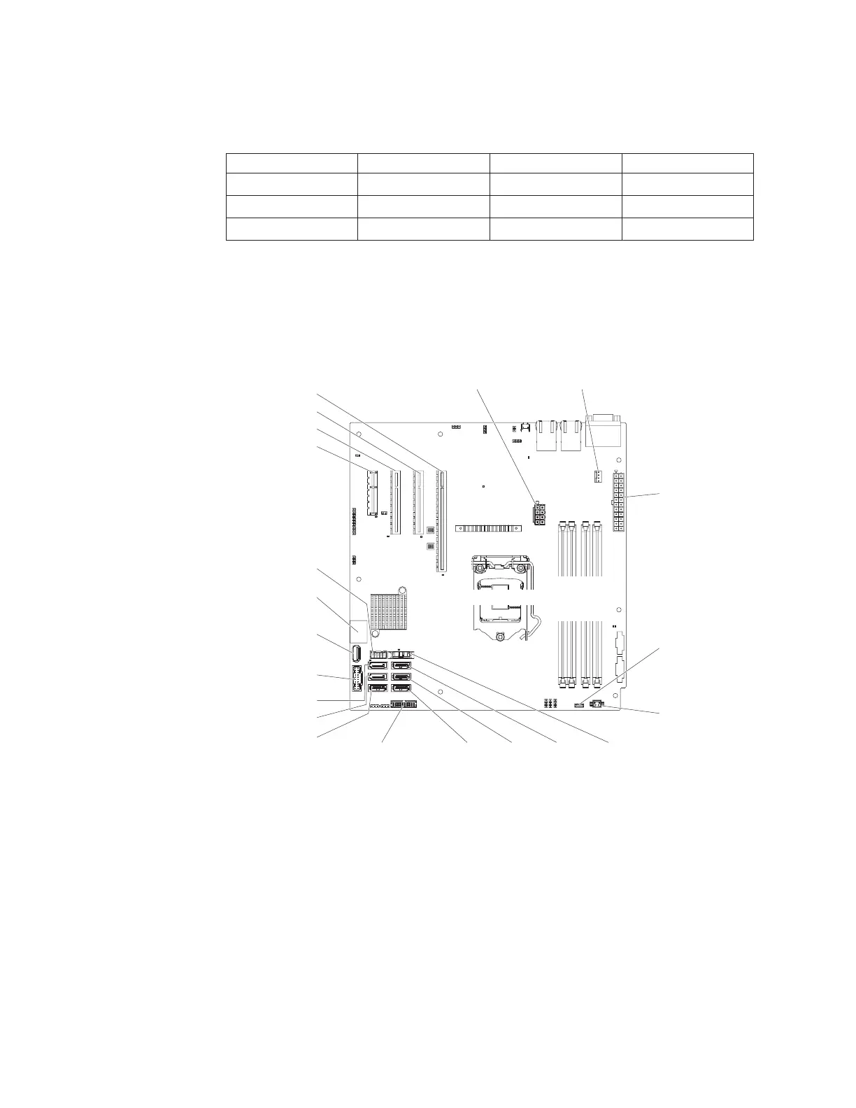
The following illustration shows the location of the DIMM connectors on the
system board.
Note: The illustrations in this document might differ slightly from your model.
Attention: Static electricity that is released to internal server components when
the server is powered on might cause the server to halt, which might result in the
loss of data. To avoid this potential problem, always use an electrostatic-discharge
wrist strap or other grounding system when you work inside the server with the
power on.
To install a DIMM on 4U server models with non-hot-swap power supplies,
complete the following steps. For the 5U server model with hot-swap power
supplies, please see the next sub-section.
1. Read the safety information in “Safety” on page vii and “Installation
guidelines” on page 35.
Fan 1 connector
Power supply
connector
Microprocessor
power connector
HDD backplane
power connector
Operator information
panel connector
S ATA 2 S ATA 1 S ATA 0
S ATA 3
S ATA 4
S ATA 5
Front USB
connector
USB tape drive
connector
USB hypervisor
connector
PCI slot 1
PCI slot 2
PCI slot 3
PCI slot 4
Battery
Fan 2 connector
Microprocessor
DIMM 1
DIMM 2
DIMM 3
DIMM 4
Thermal
sensor
connector
Figure 25. DIMM connectors on system board
46 System x3100 M5 Type 5457: Installation and Service Guide
 Loading...


