FC6A S
ERIES
MICROS
MART
L
ADDER
P
ROGRAMMING
M
ANUAL
FC9Y-B1726 18-73
18: P
ULSE
O
UTPUT
I
NSTRUCTIONS
Settings
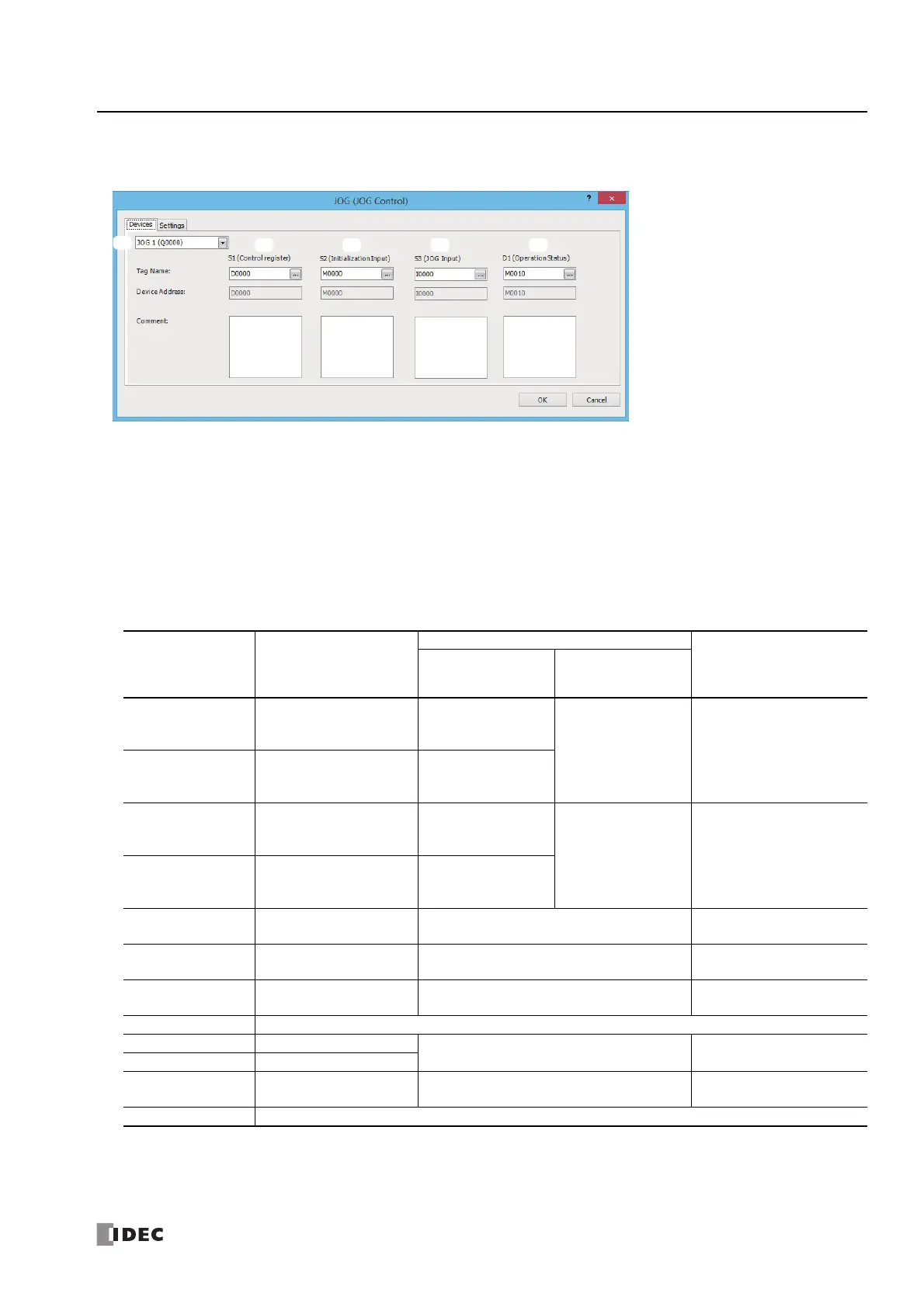
■ Devices tab
1. Select instruction
This item selects which JOG instruction to use ("JOG1", "JOG2", "JOG3", or "JOG4").
The output and reversible control mode that can be selected differ by the instruction and CPU module type.
For limitations due to the combination of instruction, reversible control mode, and the pulse output mode, see "10. Reversible
control enable" on page 18-75.
2. S1 (source 1): Control register
S1 specifies the first data register of the data registers to use with the JOG1, JOG2, JOG3, or JOG4 instruction.
Starting from the specified data register, 12 continuous words of data registers are used.
Specify the first data register so that the device range is not exceeded.
Storage
Destination
Function
Setting
Reference
All-in-One CPU
Module
CAN J1939 All-in-
One CPU Module/
Plus CPU Module
Starting number+0
Steady pulse frequency
(high word)
*1
JOG1, JOG2:
15 to 100,000
(increments of 1 Hz)
JOG1 to JOG4:
15 to 100,000
(increments of 1 Hz)
"6. Steady pulse frequency" on
page 18-75
Starting number+1
Steady pulse frequency
(low word)
*1
JOG3, JOG4:
15 to 5,000
(increments of 1 Hz)
Starting number+2
Initial pulse frequency
(high word)
*1
JOG1, JOG2:
15 to 100,000
(increments of 1 Hz)
JOG1 to JOG4:
15 to 100,000
(increments of 1 Hz)
"7. Initial pulse frequency" on
page 18-75
Starting number+3
Initial pulse frequency
(low word)
*1
JOG3, JOG4:
15 to 5000
(increments of 1 Hz)
Starting number+4 Acceleration time 10 to 10,000 (ms)
"8. Acceleration time" on page
18-75
Starting number+5 Deceleration time 10 to 10,000 (ms)
"9. Deceleration time" on page
18-75
Starting number+6 Control direction
0: Forward
1: Reverse
"11. Control direction" on
page 18-76
Starting number+7 Reserved
Starting number+8 Current value (high word)
*1
1 to 100,000,000 pulses
*2
"12. Current value" on page
18-76
Starting number+9 Current value (low word)
*1
Starting number+10 Error status 0 to 3
"13. Error status" on page 18-
76
Starting number+11 Reserved
*1 The upper and lower data registers change according to the 32-bit data storage method specified. For details, see "32-bit Data Storage" on
page 3-9.
*2 When starting pulse output, the current value is reset.
1.
2. 3. 4. 5.

 Loading...