18 Installation, Support, and Maintenance Guide
Evolution X1 Satellite Router
X1 Router (Indoor) Interfaces
4.1 X1 Router (Indoor) Interfaces
The X1 Router (Indoor) front panel indicators are described in Section 4.1.1 and the rear
panel is described in Section 4-2.
4.1.1 X1 Router (Indoor) Front Panel Power and Network LED
Status Indicators
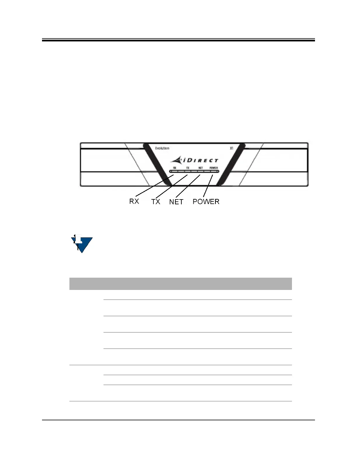
Once the X1 Router (Indoor) is powered up with the appropriate Options file, check the LEDs
to confirm the router is functioning properly. The front panel indicators are shown in
Figure 4-1 and described in Table 4-1.
Figure 4-1. X1 Router (Indoor) Front Panel Indicators
NOTE: The LED displayed colors (red, yellow, green) indicate the state of the
X1 Router and are documented in the iDX Web iSite User Guide, iDX Satellite
Router Installation and Commissioning Guide, and iDX Release Notes. The
definitions of the states may be software version dependent.
Table 4-1. X1 Router (Indoor) Panel LED Indicators
LED Label LED Color Indicated X1 Status
RX Off Receiver is disabled or not configured.
Solid Yellow Downstream carrier is configured, but the
demodulator is not locked.
Slow Flashing Yellow Downstream carrier is configured and the
demodulator is locked. NCR is not locked.
Solid Green Downstream carrier is configured,
demodulator and NCR are locked.
Flashing Red All LEDs simultaneously flashing red indicates
a software exception or bad options file.
TX Solid Yellow Transmitter is disabled.
Solid Green Transmitter is enabled.
Flashing Red All LEDs simultaneously flashing red indicates
a software exception or bad options file.