Installation, Support, and Maintenance Guide 69
Evolution X1 Satellite Router
Appendix D DC Power
Supply Installation
This appendix describes the installation of the DC power supply wiring for the X1 Router
(Indoor), Option 2.
A summary of the parts are listed in Table D-1. Follow the at a glance instructions in
Figure D-1and for detailed instructions in Table D-2.
CAUTION: If negative voltages are used such as Telecom -48VDC, the negative
most voltage is always connected to –ve terminal (in the Telecom case this would
be -48V) and the positive most voltage is always connected to the +ve terminal (in
the Telecom case this would be 0VR). The Chassis can be referenced to +ve, -ve
or left floating (i.e. not connected to either +ve or –ve) as required because the
power module is fully isolated input to chassis.
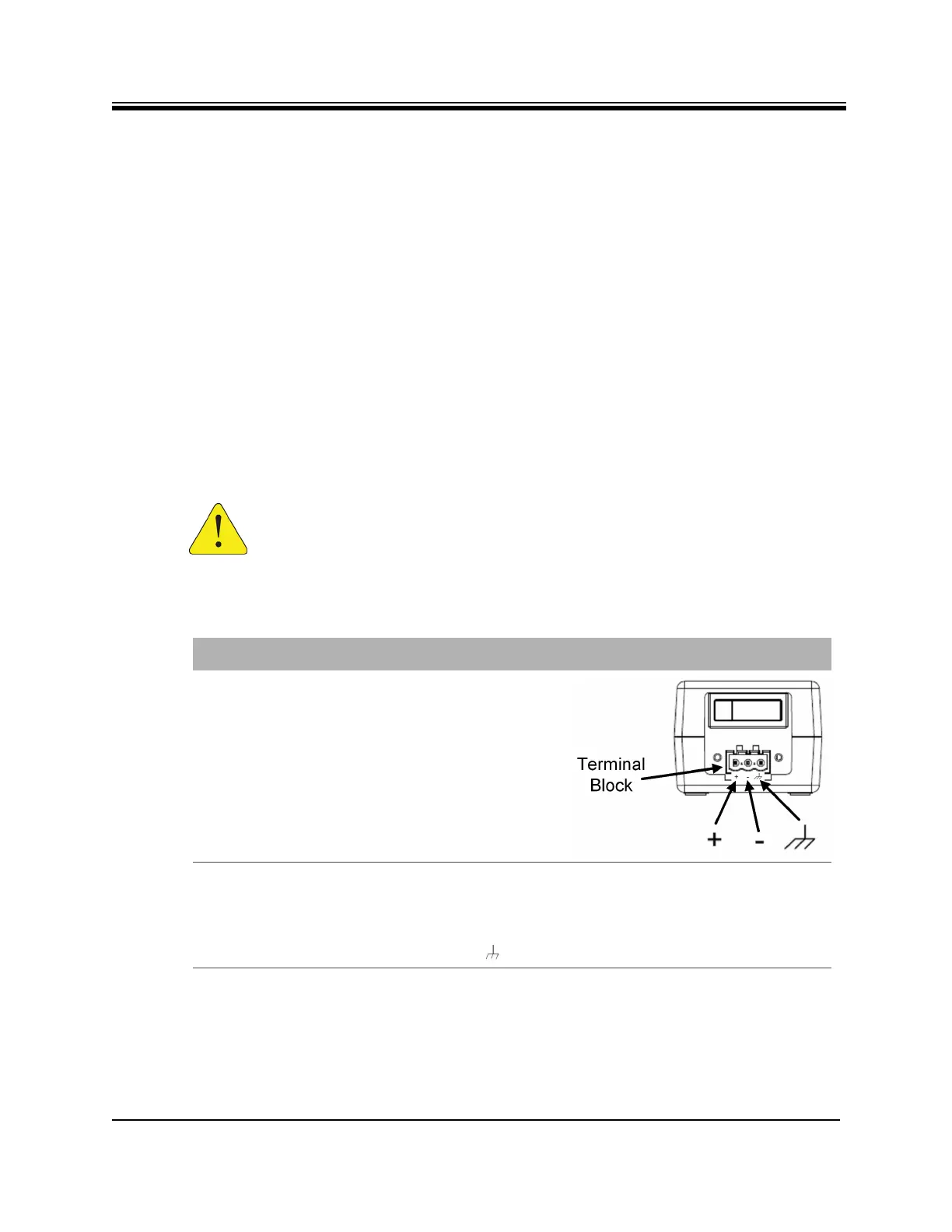
Table D-1. X1 Router (Indoor) DC Power Module Connector Parts
Name Description Diagram or Reference
DC Terminal block Rear panel,
DC terminal block area
3 DC input wires Appropriately labeled wires,
such as:
• red = positive +
• black = negative -
• blue = ground -
14-18 AWG (American Wire Gauge)
Reference:
http://en.wikipedia.org/wiki/America
n_wire_gauge