46 Installation, Support, and Maintenance Guide
Evolution X1 Satellite Router
Connecting the DC Power Module
6.9.2 Connecting Power Supply to The Power Module
Table 6-4 on page 47 shows the detailed installation steps for the Power Module and gland
assembly and Figure 6-9 shows a blow up of the gland assembly parts.
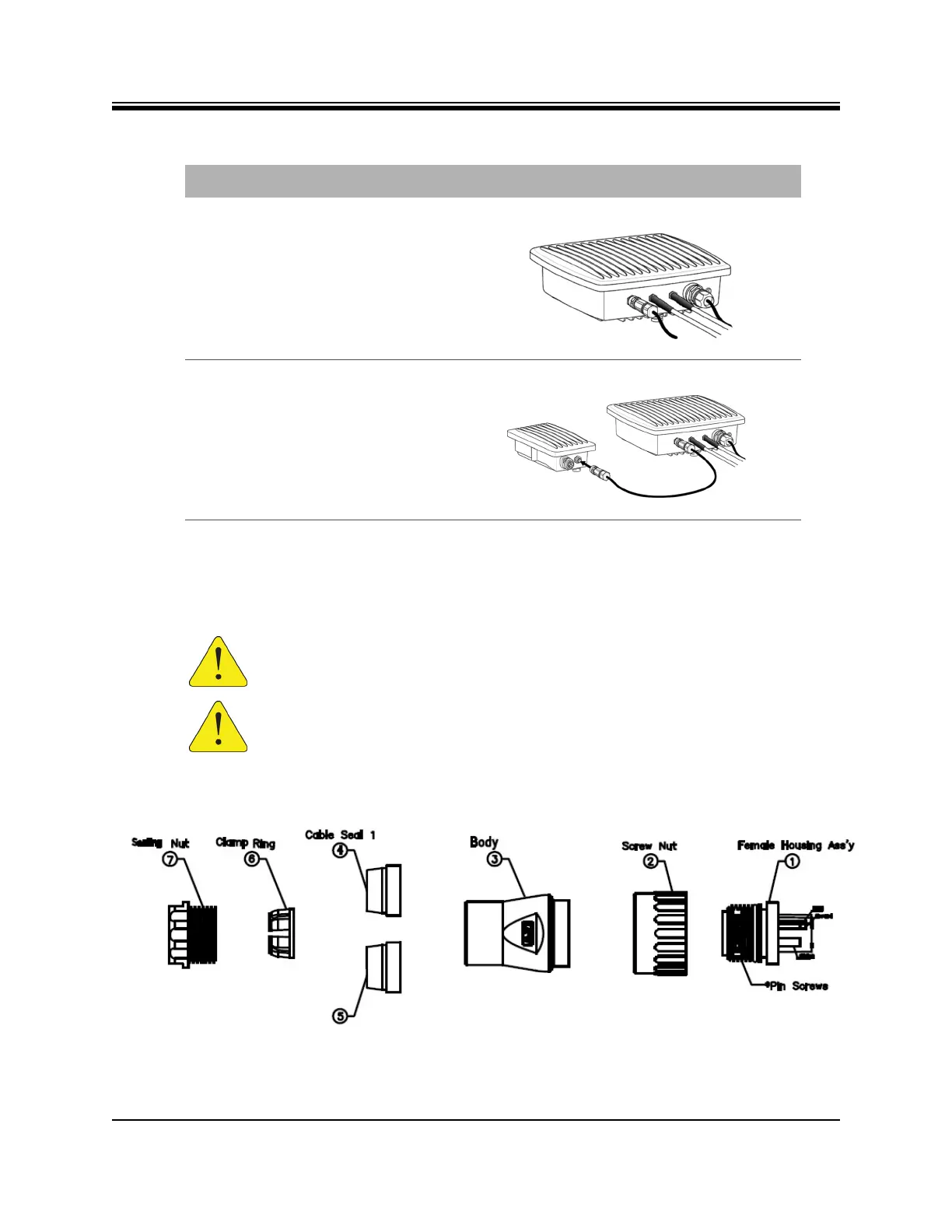
Figure 6-9. Power Gland Assembly
2.
Final X1 Outdoor Router DC power
connection completed; proceed to
step 3.
3.
Lock the opposite end of the DC
power cord into the Power
Module.
CAUTION: Install power on a GFI (Ground Fault Interrupter) protected circuit.
CAUTION: All cables should be installed with a drip loop or service loop.
Table 6-3. X1 Outdoor Router Power Module DC to DC Installation Instructions
Step Instructions Diagram