Installation, Support, and Maintenance Guide 63
Evolution X1 Satellite Router
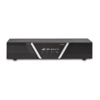
Figure B-2. Cutting Technique for Removing Foil in the Braid
4. Fold the braid back over the jacket and trim the braid to the length as defined under
Length C in Table B-1 on page 62 and shown inFigure B-3.
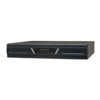
Figure B-3. Folding the Braid
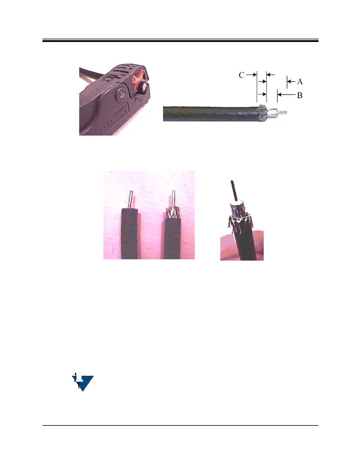
5. Flare the inner, outer braids and the outer foil shield only. Do not flare the inner foil
shield (last foil around dielectric).
6. (If using a coax stripper, skip this step.) Being careful not to cut into the copper of the
center conductor, remove the foil and cut the dielectric to the length shown under
Length B in Table B-1 on page 62. Remove any dielectric residue.
7. If the conductive foil is burred, then smooth out the burr so that the edge (area where the
dielectric material was removed) is smooth and provides a lead-in for the connector
mandrel.
8. Install the RG-6 connector compression sleeve, or mandrel, (top left (A) in Figure B-4 on
page 64) over foil and underneath the braid. A good, weatherproof outdoor connector
mandrel should have a visible O-Ring (bottom right (B) Figure B-4 on page 64).
9. Since the RG-11 connector has a built-in center pin, ensure that the coax center pin
makes contact to the internal seizing pin of the connector. Refer to Figure C-3.
NOTE: The white colored inner dielectric insulation should be flush with the
inner rear surface of the connector. Refer to the picture on the right (C) in
Figure B-4 on page 64 for an RG-6/RG-11 termination.