70 Installation, Support, and Maintenance Guide
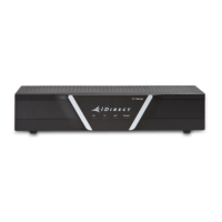
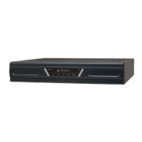
Evolution X1 Satellite Router
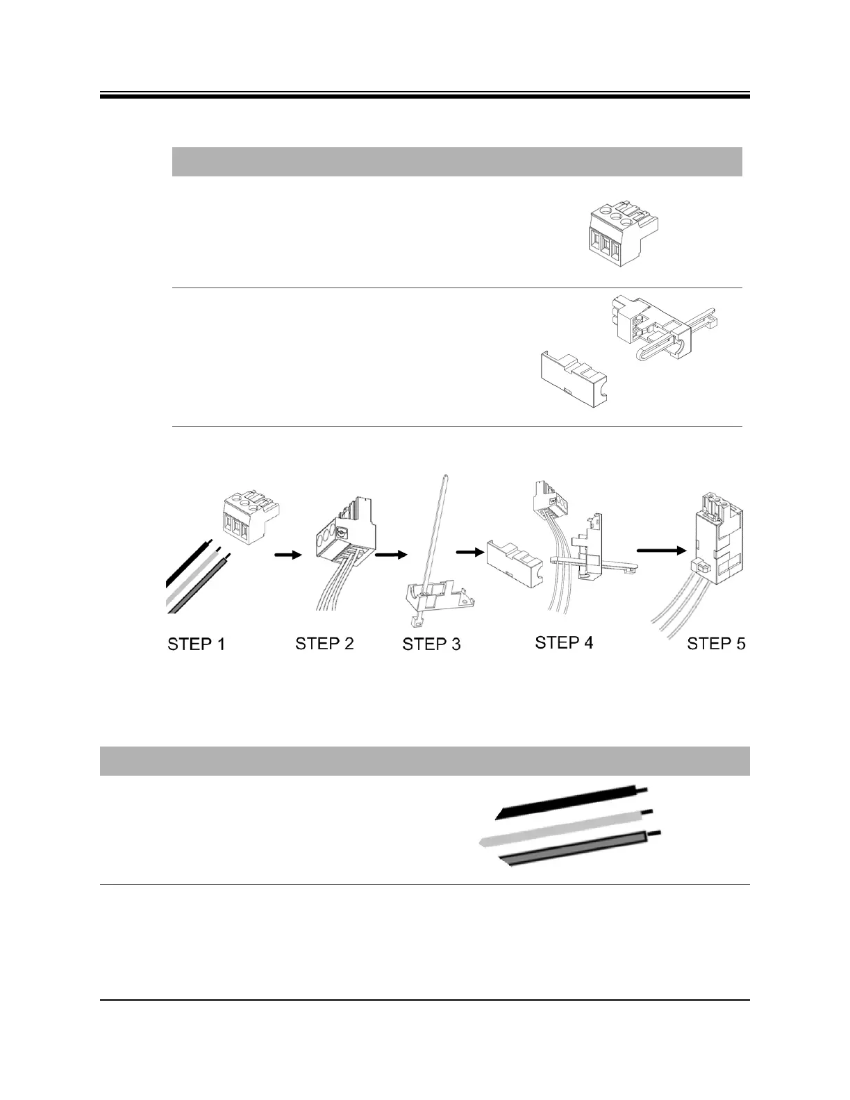
Figure D-1. DC-DC Power Supply Assembly at a Glance
Terminal block plug Included in kit, P/N Phoenix
1754465
Cable Entry Housing
Strain Relief and
Cable Tie
Cable Entry Housing Strain
Relief and Cable Tie, included
in kit, P/N 1803947, and cable
tie
Table D-1. X1 Router (Indoor) DC Power Module Connector Parts
Name Description Diagram or Reference
Table D-2. Power Module Power Cable Installation Instructions Detail
Step Instructions Diagram
1. Strip approximately 1/4 inch of insulation
from the ends of three appropriately sized
(14-18 AWG) DC input wires.