Installation, Support, and Maintenance Guide 21
Evolution X1 Satellite Router
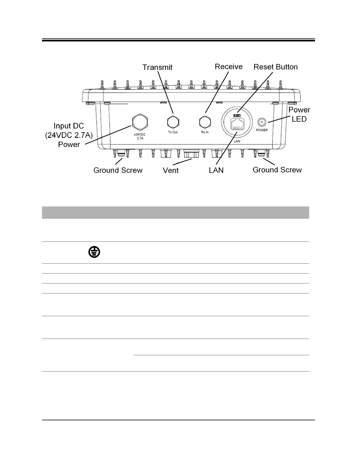
X1 Outdoor Router Interfaces
Figure 4-3. X1 Outdoor Router Panel
Table 4-3. X1 Outdoor Router Panel and LED Descriptions
Callout Label Connector Type Interface and Purpose
Input DC (24
VDC 2.7A)
Power
+24VDC
2.7A
DC connector Input DC power from the Power Module.
Ground Screw none Grounding screw (provided)
Vent none none Environmental pressure relief valve
Transmit TX Out 75 ohm, F-Type L-Band Transmit signal to Block Up Converter
Receive RX In 75 ohm, F-Type L-Band receive signal
Reset Button None Above the RJ-45
port, a small
square
Factory default reset, location of the reset button
shown in Figure 4-3 on page 21 and description of
operation in Appendix E, X1 Reset on page 73.
LAN LAN RJ-45 Ethernet LAN port connectting the X1 Router to the
customer LAN Hub switch; See Appendix C, Ethernet
and Console RJ45 Pinouts on page 65
Power LED POWER Off No or low DC power input to the X1 Outdoor
Router.
Solid Red Acceptable DC power level to the X1 Outdoor
Router is detected.