Installation, Support, and Maintenance Guide 47
Evolution X1 Satellite Router
Connecting the DC Power Module
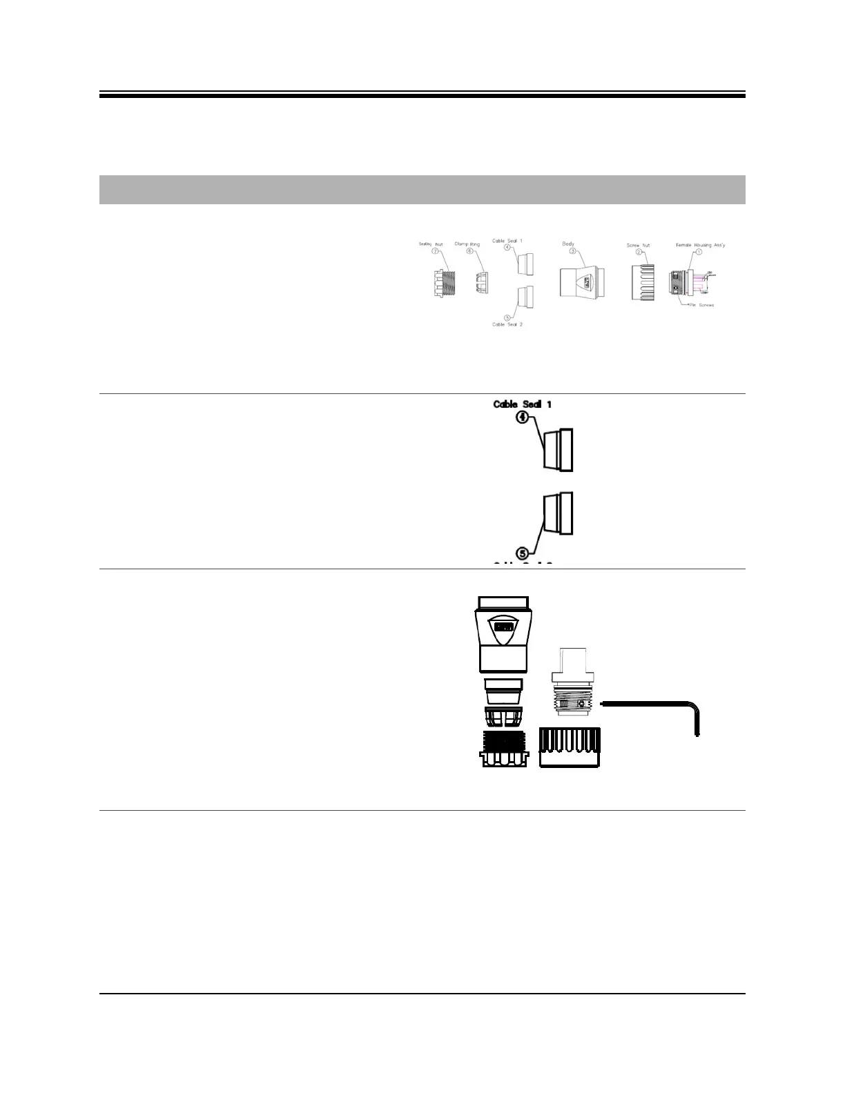
Table 6-4. Power Module Power Cable Installation Instructions
Step Instructions Diagram
1. Make sure all parts of the gland are available
1 - Female Housing Assembly (Ass’y)
2 - Screw Nut
3 - Body
4 - 6 mm (.24 in) diameter Cable Seal, which
is split for easy application to cable
5 - 12 mm (.47 in) diameter Cable Seal,
which is split for easy application to cable
6 - Clamp Ring
7 - Sealing Nut
2. Select a cable seal size (item 4 or 5, in Step
1) , providing the best fit for the diameter of
cable to be used.
3.
Table 4-6, Pin Assignments for AC Power
Module Gland (4 pin) on page 23 and
Table 4-7, Pin Assignments for DC Power
Module Gland (4 pin) on page 23 shows the
pin assignments for the AC and DC,
respectively, power wires in the Female
Housing Assembly.
1. Connect the AC or DC wires into the
assembly according to the pin assignment
descriptions in Table 4-6 on page 23 (for
AC power) or Table 4-7 on page 23 (for DC
power).
2. Using the Allen Wrench (provided),
tighten the pin screws for each of the
power wires in the Female Housing
Assembly.