Installation, Support, and Maintenance Guide 19
Evolution X1 Satellite Router
X1 Router (Indoor) Interfaces
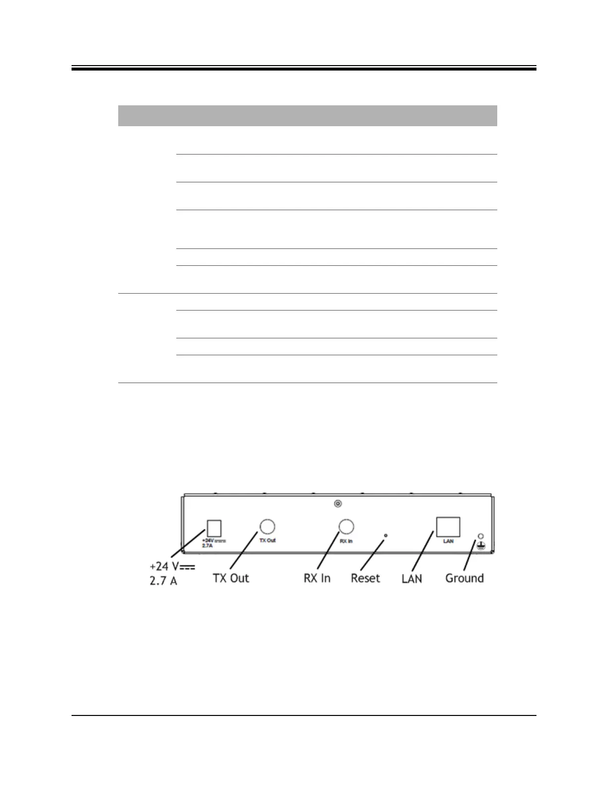
4.1.2 X1 Router (Indoor) Rear Panel
This section describes and illustrates the rear panel connectors and LED indicators. They are
shown in Figure 4-2 and defined in Table 4-2 on page 20. The LAN/RJ45 pin assignments are
listed in Appendix C, Ethernet and Console RJ45 Pinouts on page 65.
Figure 4-2. X1 Router (Indoor) Rear Interface Connectors
NET Flashing Yellow Demodulator is not locked on the Downstream
carrier.
Solid Yellow Demodulator is locked on the Downstream
carrier.
2 Second Flashing Green Demodulator is locked on the Downstream
carrier. Network acquisition is in progress.
1 Second Flashing Green Demodulator and NCR are locked on the
Downstream carrier. Network acquisition is in
progress.
Solid Green Network is acquired. Link Layer is up.
Flashing Red All LEDs simultaneously flashing red indicates
a software exception or bad options file.
POWER Off No or low DC power input to the X1.
Solid Green Acceptable DC power level to the X1 is
detected.
Solid Yellow BUC/LNB power fail.
Flashing Red All LEDs simultaneously flashing red indicates
a software exception or bad options file.
Table 4-1. X1 Router (Indoor) Panel LED Indicators (continued)
LED Label LED Color Indicated X1 Status