36 Installation, Support, and Maintenance Guide
Evolution X1 Satellite Router
Installation with AC (Option 1) or DC (Options 2 and 3) Power Supplies
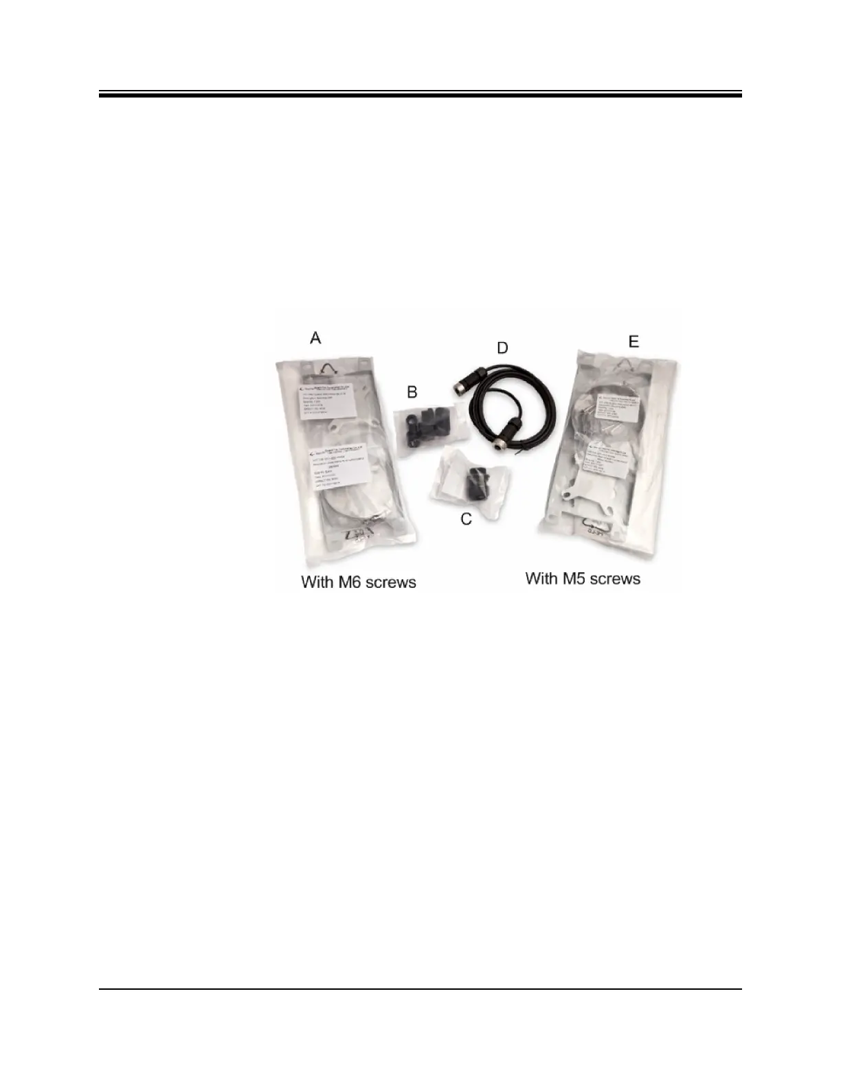
• One (1) LAN Ethernet gland, see Figure 6-1 on page 36, item labeled C
• One (1) DC 6 foot power cable, see Figure 6-1 on page 36, item labeled D
• Additional components normally required are:
• One antenna
• IFL (Inter Facility Link) or Coaxial cable appropriate for the installation
• One appropriate feed assembly for the antenna (OMT)
• One BUC (Block Up Converter)
• One LNB (Low Noise Block Converter)
Figure 6-1. Packaged Items
6.4 Installation with AC (Option 1) or DC (Options 2
and 3) Power Supplies
This section describes installation with either an AC power Supply (Option 1) or a DC Power
supply (Option 2 or 3).
6.4.1 Installation with AC Power Supply to the Power Module -
Option 1 (AC)
For an X1 Outdoor Router with an AC power supply:
1. Assemble the AC power gland, as described in Section 6.9.2, Connecting Power Supply to
The Power Module on page 46, using the AC Pin assignments in Table 4-6.
2. Connect the AC power gland assembly to the Power Supply Connector on the Power
Module, labeled 100-240 VAC, 1.2 A 50/60 Hz. See Figure 4-4 on page 22 for Power
Module connector descriptions.