Installation, Support, and Maintenance Guide 23
Evolution X1 Satellite Router
X1 Outdoor Router Interfaces
DC (24VDC 2.7A)
Power Connector to
Router
Option 1: 24 VDC 2.7 A
Options 2 & 3: 24 V 2.7 A
DC power connector to Router
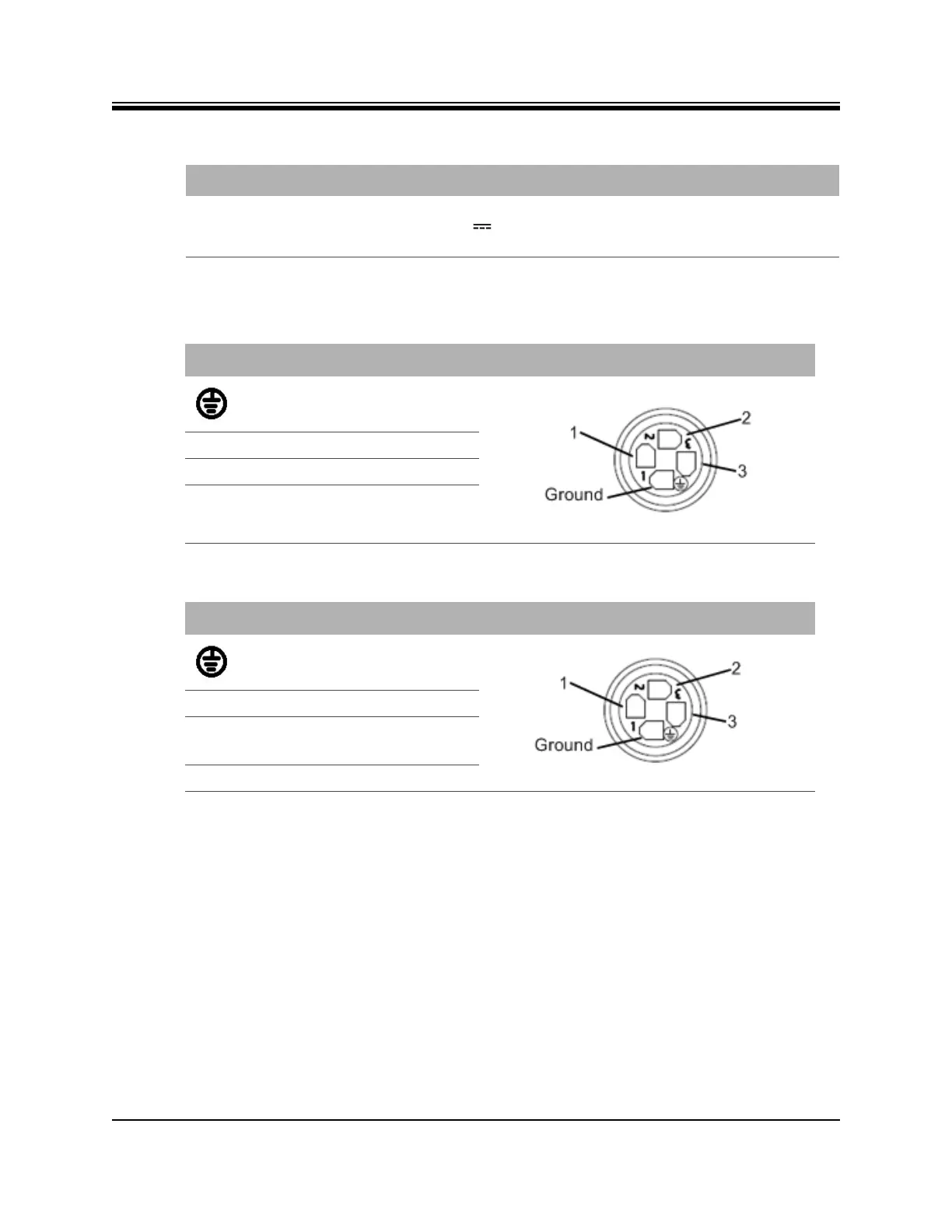
Table 4-6. Pin Assignments for AC Power Module Gland (4 pin)
Pin Definition Diagram
Ground (Pin 4)
1 Option 1: Live (L), 100-240 VAC
2 Do Not Use
3 Neutral
Table 4-7. Pin Assignments for DC Power Module Gland (4 pin)
Pin Definition Diagram
Ground (Pin 4)
1 Do Not Use
2 Option 2: +12-36 VDC
Option 3: +36-76 VDC
3 DC Return
Table 4-5. X1 Outdoor Router Power Module Connector Descriptions
Callout Label Description