Installation, Support, and Maintenance Guide ix
Evolution X1 Satellite Router
Figures
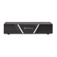
Figure 1-1. Front View of the iDirect Evolution X1 Satellite Router (Indoor) . . . . . . . . . . . . . 1
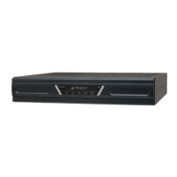
Figure 1-2. X1 Outdoor Router (Left), and the Power Module (Right) . . . . . . . . . . . . . . . . . 2
Figure 4-1. X1 Router (Indoor) Front Panel Indicators . . . . . . . . . . . . . . . . . . . . . . . . . . . 18
Figure 4-2. X1 Router (Indoor) Rear Interface Connectors . . . . . . . . . . . . . . . . . . . . . . . . 19
Figure 4-3. X1 Outdoor Router Panel . . . . . . . . . . . . . . . . . . . . . . . . . . . . . . . . . . . . . . 21
Figure 4-4. X1 Outdoor Router Power Module with Connectors Labeled . . . . . . . . . . . . . . . 22
Figure 6-1. Packaged Items . . . . . . . . . . . . . . . . . . . . . . . . . . . . . . . . . . . . . . . . . . . . 36
Figure 6-2. Router Mounting Kit Parts . . . . . . . . . . . . . . . . . . . . . . . . . . . . . . . . . . . . . 38
Figure 6-3. Attaching the Mounting Plate . . . . . . . . . . . . . . . . . . . . . . . . . . . . . . . . . . . 39
Figure 6-4. X1 Outdoor Router Wall Mount . . . . . . . . . . . . . . . . . . . . . . . . . . . . . . . . . . 39
Figure 6-5. X1 Outdoor Router Pole Mount . . . . . . . . . . . . . . . . . . . . . . . . . . . . . . . . . . 40
Figure 6-6. Mounting the Power Module . . . . . . . . . . . . . . . . . . . . . . . . . . . . . . . . . . . . 41
Figure 6-7. Power Module Wall Mount . . . . . . . . . . . . . . . . . . . . . . . . . . . . . . . . . . . . . 41
Figure 6-8. Power Module Pole Mount . . . . . . . . . . . . . . . . . . . . . . . . . . . . . . . . . . . . . 42
Figure 6-9. Power Gland Assembly . . . . . . . . . . . . . . . . . . . . . . . . . . . . . . . . . . . . . . . 46
Figure A-1. Installation Tools . . . . . . . . . . . . . . . . . . . . . . . . . . . . . . . . . . . . . . . . . . . 58
Figure B-1. Coax Cable Cutting Technique . . . . . . . . . . . . . . . . . . . . . . . . . . . . . . . . . . 62
Figure B-2. Cutting Technique for Removing Foil in the Braid. . . . . . . . . . . . . . . . . . . . . . 63
Figure B-3. Folding the Braid . . . . . . . . . . . . . . . . . . . . . . . . . . . . . . . . . . . . . . . . . . . 63
Figure B-4. Attaching the Compression fitting F-type Connector . . . . . . . . . . . . . . . . . . . . 64
Figure B-5. Compression fitting F-Type Weatherproof Plugs and Tool . . . . . . . . . . . . . . . . 64
Figure C-1. RJ-45 Cable Connectors, Plug and Receptacle . . . . . . . . . . . . . . . . . . . . . . . . 65
Figure C-2. Holding the RJ-45 Cable Connectors . . . . . . . . . . . . . . . . . . . . . . . . . . . . . . 66
Figure C-3. RJ-45 to DB-9 Female DTE Adapter . . . . . . . . . . . . . . . . . . . . . . . . . . . . . . . 67
Figure D-1. DC-DC Power Supply Assembly at a Glance . . . . . . . . . . . . . . . . . . . . . . . . . . 70