LOCAL OPERATION
3-6 46882/439
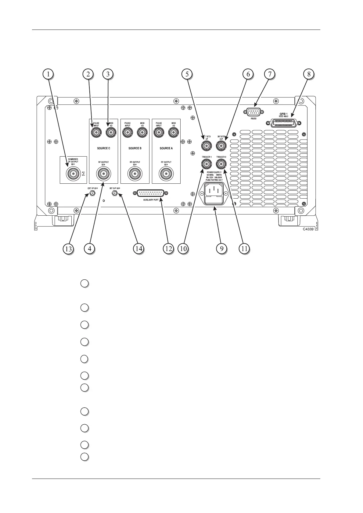
Rear-panel connectors
The rear-panel connectors are shown in Fig. 3-2 below.
Fig. 3
-2 2026 rear panel
1
COMBINED RF
OUTPUT (optional)
An Option 4 50 Ω type
-N connector. When fitted, replaces the
front-panel connector.
2
PULSE INPUT
(optional)
An Option 4 10 kΩ BNC connector. When fitted, replaces the
front-panel connector.
3
MOD I/O (optional)
An Option 4 100 kΩ BNC connector. When fitted, replaces the
front-panel connector.
4
RF OUTPUT
(optional)
An Option 4 50 Ω type
-N connector. When fitted, replaces the
front-panel connector.
5
EXT STD I/P BNC connector for the input of an external standard frequency
of either 1 MHz or 10 MHz.
6
INT STD O/P BNC connector for the output of the internal 10 MHz standard.
7
RS232 9
-way RS-232 connector used for remote control of the
instrument as well as to reprogram the internal flash memory.
For contact allocation see ‘RS
-232 connector’ in Chapter 2.
8
GPIB 1 24
-pin socket accepts standard IEEE connector to allow remote
control of the instrument.
9
POWER SUPPLY 3
-pin plug integral with fuse holder. Mates with AC supply
lead socket.
10
TRIGGER 1 BNC connector which is used for sweep triggering.
11
TRIGGER 2 Reserved.
 Loading...