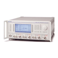
LOCAL OPERATION
46882/439 3-5
1
SUPPLY Switches the AC supply voltage on and off.
2
[A], [B], [C] This key is repeated for each signal source. It selects A, B or C
as the current signal source for parameter display and
adjustment. The C source is optional.
3
[SETUP] Displays the Setup Menu used for signal source configuration
and for selecting an application mode..
4
[SIG GEN] Displays the main, Sig Gen, menu.
5
[SWEEP] Displays the Sweep Control screen for the current source.
6
[UTIL] Displays the Utilities Selection Menu.
7
[MEM] Displays the Memory Store/Recall Menu.
8
[TOTAL Δ]
Displays the Total Shift Menu for the current source.
9
Soft keys Twelve function keys change notation as the menus change.
10
Numerical key pad For entering the value of a selected parameter. Minus sign and
decimal point are included.
11
[ENTER]/Units keys Determine the units of the set parameters and also used to
terminate a numerical entry.
12
[KNOB LOCK] Pressing this key assigns control knob operation to the
currently selected function.
13
Control knob When enabled by the [KNOB ON/OFF] key, adjusts the value
of the selected parameter.
14
[KNOB ON/OFF] Enables or disables the control knob.
15
[×10]
When control knob enabled, decreases knob resolution by a
factor of 10.
16
[÷10]
When control knob enabled, increases knob resolution by a
factor of 10.
17
[SET Δ]
Displays the Steps Menu for the current source.
18
[×] Increments the value of the selected parameter.
19
[Ø] Decrements the value of the selected parameter.
20
PULSE INPUT
10 kΩ BNC connector (fitted to each signal source) which
accepts a pulsed input.
21
MOD I/O
100 kΩ BNC connector (fitted to each signal source) which
allows an external modulating signal to be applied.
Also provides a modulation oscillator output from a 600 Ω
source impedance.
With Option 4 this connector is fitted on the rear panel.
22
[Σ]
Displays the Combiner Summary.
23
[RF ON/OFF] Enables or disables the associated signal source RF OUTPUT
or the COMBINED RF OUTPUT connector.
24
RF OUTPUT
50 Ω type
-N connector (fitted to each signal source). Protected
against the application of reverse power of up to 50 W.
With Option 4 this connector is fitted on the rear panel.
25
COMBINED RF
OUTPUT
50 Ω type
-N connector. Note that maximum reverse power at
this connector is 0.5 W. With Option 4 this connector is fitted
on the rear panel.

 Loading...