22
HDK-99 1803 VER1 (E)
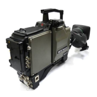
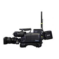
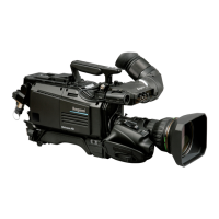
2.1 Camera and Viewfinder
①
GREEN TALLY indicator
Lights when the GREEN TALLY signal is input to the CCU.
②
RED TALLY indicator
Lights when the RED TALLY signal is input to the CCU. It also lights when the CALL
button on the CCU, or control panel is pressed.
③
REAR TALLY switch
Turns ON/OFF the GREEN TALLY and RED TALLY indicators.
ON : Activates lighting function of GREEN and RED TALLY indicators.
OFF : Deactivates lighting function of GREEN and RED TALLY indicators.
④
CALL button
Calls an operator. When this button is pressed, the RED TALLY lamps on the CCU, and
control panel light and a buzzer sounds.
⑤
INTERCOM FRONT VR SELECT switch
Species whether to use the right side controls (INTERCOM MIC switch, INTERCOM
PGM control knob, and INTERCOM PHONE control knob) or the controls on the rear of
the camera for controlling the intercom volume and push to talk functions.
INTERCOM-1 : Enables the use of the right side controls to control the INTERCOM-1
headset volume. The INTERCOM-2 headset volume is controlled by the
controls on the rear of the camera.
OFF : Disables the use of the right side controls to control intercom. The
volume is controlled by the controls on the rear of the camera.
INTERCOM-2 : Enables the use of the right side controls to control the INTERCOM-2
headset volume. The INTERCOM-1 headset volume is controlled by the
controls on the rear of the camera.
⑥
INTERCOM-2 control knob
Controls the intercom volume of the channels allocated to the connector.
⑦
INTERCOM-2 MIC switch
Turns ON/OFF the INTERCOM-2 intercom microphone.
ON : Turns ON the intercom microphone.
OFF : Turns OFF the intercom microphone.
PTT : Turns ON the intercom microphone while this switch is pressed.
⑧
INTERCOM-2 PGM2 control knob
Controls the PGM2 volume of the INTERCOM-2 program intercom.
⑨
INTERCOM-2 PGM1 control knob
Controls the PGM1 volume of the INTERCOM-2 program intercom.
⑩
INTERCOM-2 connector
Connects the INTERCOM-2 intercom headset. It is compatible with XLR series connectors.
⑪
EARPHONE jack
Connects a headset equipped with a mini plug. Voice can be heard when VTR is played
back.
⑫
I/O connector
A multi-pin for input/output signals including GREEN/RED TALLY control output signals,
RET-1/RET-2 control input signals, and RS-422 data control signals.
Note:
You can select the sound you
want to hear in the
ENGINEER
menu (P95)
.
Reference:
Refer to
"7. SPECIFICATIONS
: I/O Connector" (P142)
for the pin functions of the I/O
connector.