SD1 Series Inverters Communication Protocol
-132-
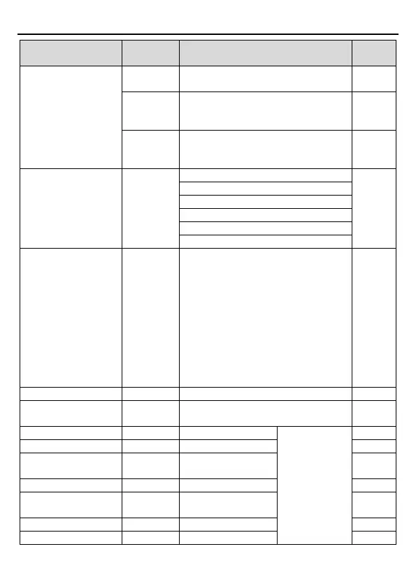
Function instruction
Data meaning instruction
(0~
1000, 1000 corresponds to the
100.0% of the rated voltage of the motor)
200DH
(-1000~
1000, 1000 corresponds to
100.0%)
R/W
200EH
AO output setting 2
(-1000~1000, 1000
R/W
SW 1 of the inverter 2100H
R
0006H: Pre-exciting state
SW 1 of the inverter 2101H
Bit0: =0: bus voltage is not established
=1: bus voltage is established
Bi1~2: =00: motor 1 =01: motor 2
=10: motor 3 =11: motor 4
Bit3: =0: asynchronous motor =1:
synchronous motor
Bit4: =0: pre-alarm without overload =1:
overload pre-alarm
Bit5~ Bit6:=00: keypad control
=01: terminal control
=10: communication control
R
See the fault type instruction
Identifying code of the
inverter
2103H SD1-----0x0180 R
Compatible with
the
communication
addresses of
GD, CHF100A,
and CHV100
series.
Bus voltage 3002H
0.0~2000.0V, unit:
R
Output current 3004H
0.0~3000.0A, unit:
R