SD1 Series Inverters Function Parameters
-44-
Name Description Default
Modify
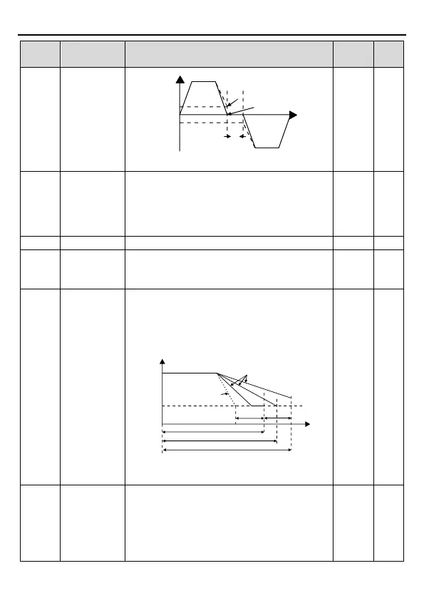
Output frequency
FWD
REV
T
Starting
frequency
Shift after the
zero frequency
Shift after the
starting frequency
Setting range: 0.0~3600.0s
P01.14
FWD/REV
Set the threshold point of the inverter:
0: Switch at zero frequency
1: Switch at the start frequency
2: Switch after the speed reaches the stop speed
(P01.15) for the set the delay (P01.24)
1 ◎
◎
P01.16
Detection of
stopping speed
0: Detect at the setting speed
1: Detect at the feedback speed (valid only for
1 ◎
P01.17
Detection time
of the feedback
speed
When P01.16=1, the actual output frequency of
the inverter is less than or equal to P01.15 and is
detected during the time set by P01.17
inverter will stop; otherwise, the inverter
the time set by P01.24.
T
Stop speed
A
Ramp reference
frequency
Output frequency
Frequency
P01.24 P01.17
B
C
Running A
Running B
Running C
Setting range: 0.00~100.00s (valid only when
.50
s
◎
P01.18
Power-on
terminal
running
protection
selection
When the running command channel is the
terminal control, the system will detect the state
of the running terminal during powering on.
0: The terminal running command is invalid when
powering on. Even the running command is
detected to be valid during powering on, the
0 ○