SD1 Series Inverters Function Parameters
-63-
Name Description Default Modify
switching off
P05.32
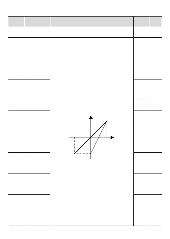
AI1 is set by the analog potentiometer, AI2 is set
by control terminal AI2 and AI3 is set by control
terminal AI3. The function code defines the
relationship between the analog input voltage
and its corresponding set value. If the analog
input voltage beyo
maximum input value, the inverter
the minimum or maximum one.
When the analog input is the current input, the
corresponding voltage of 0~20mA is 0~10V.
In different cases, the corresponding rated value
of 100.0% is different. See the application for
detailed information.
The figure below illustrates different applications:
Corresponding
setting
100%
-100%
-10V
Al3
AI1/AI2
20mA
AI
10V
Input filter time: this parameter is used to adjust
t
he sensitivity of the analog input. Increasing the
value properly can enhance the anti-interference
of the analog, but weaken the sensitivity of the
analog input
Note: AI1 supports 0~
supports 0~10V or 0~
selects 0~20mA input, the corresponding voltage
of 20mA is 10V. AI3 can support the output of
-10V~+10V.
Setting range of P05.32: 0.00V~P05.34
Setting range of P05.33: -100.0%~100.0%
0.00V ○
P05.33
setting of the
lower limit of
0.0% ○
P05.34
10.00V ○
P05.35
setting of the
upper limit of
100.0% ○
P05.36
0.100s ○
P05.37
Lower limit of
0.00V ○
P05.38
setting of the
lower limit of
0.0% ○
P05.39
Upper limit of
10.00V ○
P05.40
setting of
100.0% ○
P05.41
AI2 input filter
0.100s ○
P05.42
○
P05.43
setting of the
lower limit of
-100.0
%
○
P05.44
0.00V ○