SD1 Series Inverters Function Parameters
-78-
Name Description Default Modify
output the signal of "running time arrival".
Setting range: 0~65535min
P08.28
The time of the fault reset: set the fault reset time
by selecting this function. If the reset time
exceeds this set value, the inverter
the fault and wait to be repaired.
The interval time of the fault reset: The interval
between the time wh
en the fault occurs and the
time when the reset action occurs.
Setting range of P08.28: 0~10
Setting range of P08.29: 0.1~100.0s
0 ○
P08.29
Interval time of
automatic fault
reset
1.0s ○
P08.30
Frequency
decreasing
ratio in drop
control
The output frequency of the inverter
changes as
the load. And it is mainly used to balance the
power when several inverters drive one load.
Setting range: -50.00Hz~50.00Hz
0.00Hz ○
P08.32
FDT1
electrical
level detection
value
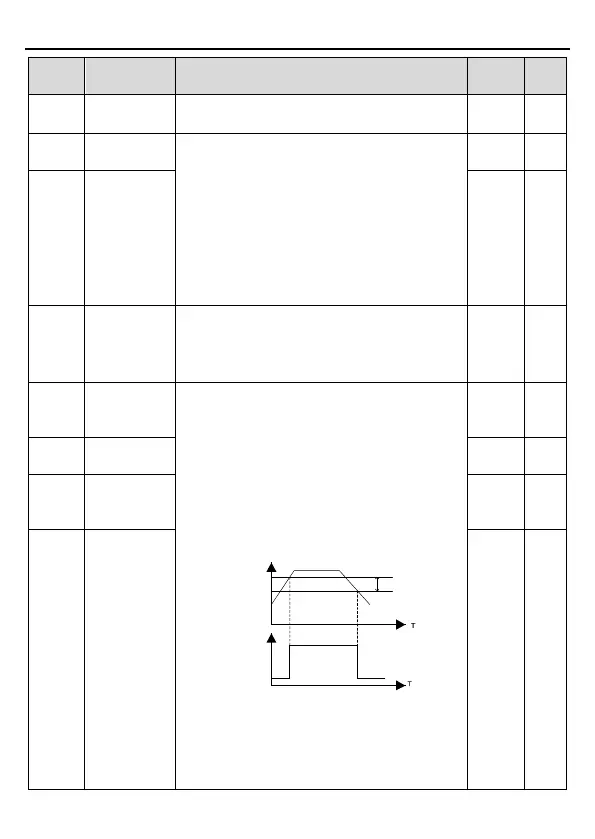
When the output frequency exceeds the
corresponding frequency of FDT electrical level,
the multi-
function digital output terminals will
output the signal of "frequency level detect FDT"
until the output frequency decreases
lower than (FDT electrical level—
FDT retention
detection value) the corresponding frequency,
the signal is invalid. Below is the waveform
diagram:
Output frequency
FDT level
Y,
RO
1, RO2
FDT lag
Setting range of P08.32: 0.00Hz~P00.03
(The max. frequency)
Setting range of P08.33 and P08.35:
0.0~100.0%
Setting range of P08.34: 0.00Hz~P00.03
50.00H
z
○
P08.33
FDT1 retention
detection value
5.0% ○
P08.34
FDT2 electrical
level detection
value
50.00H
z
○
P08.35
detection value
5.0% ○