INFICON Operation | 6
Ecotec E3000-Operating-instructions-kina22en1-28-(2211) 29 / 104
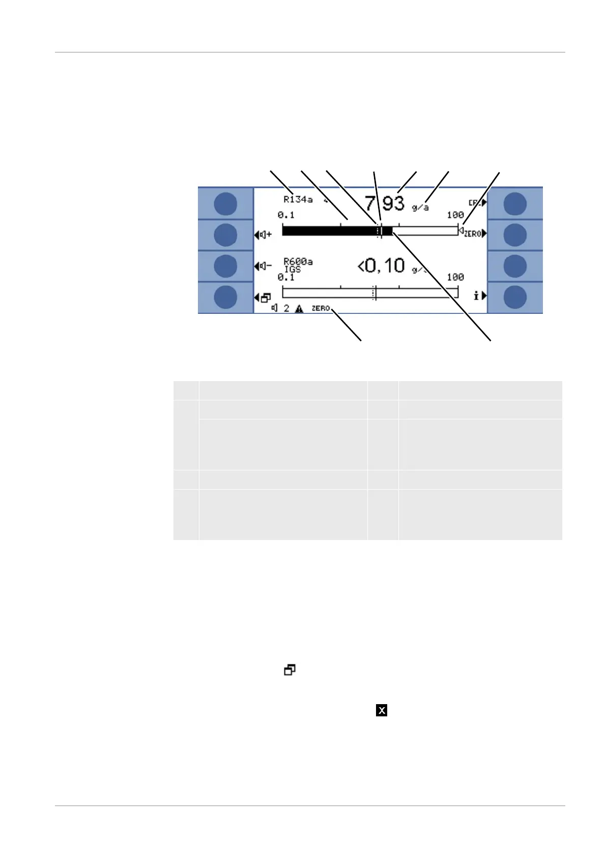
6.2.2 Measurement display elements
The measured leak rates are shown numerically and with logarithmically divided bar
graph displays. The other elements of the measurement view are shown in the
following Figure.
Fig.12: Measurement display elements
1 Gas 5 Numerical leak rate display
2 Bell: Search threshold is exceeded 6 Leak rate unit
Bell flashes: trigger value exceeded 7 Marker arrow: Marks the
measurement displayed on the
sniffer handle
3 Search threshold (broken line) 8 Bar graph, logarithmic
4 Trigger value 9 Status bar: Symbols and text
overlay provide information about
the device status
The two center buttons on the left side of the display can be used to adjust the volume
of the alarm signal at any time. If one of the two buttons is pressed, the device emits a
sound with the selected volume through the speaker and shows the setting with a bar
graph in the status line. The set value is also the first entry in the status line on the
bottom of the display and applies only to the speaker of the basic unit. To configure
various alarm profiles, see "Audio settings [}34]."
Menu button The button at the lower left of the display has two functions:
• Calls the main menu.
• Back to last window that was closed with .
Calibration button
(CAL)
The button on the top right next to the display can be used to start a calibration of the
Ecotec E3000 with an external test leak at any time. For further information on
performing an external calibration, see "External calibration with external calibrated
leak [}45]."