Page 21
Omni Installation Instructions
© Mass Electronics Pty Ltd 2017Chapter 2 – Mechanical Installation
Optional HMI shown in C20D image.
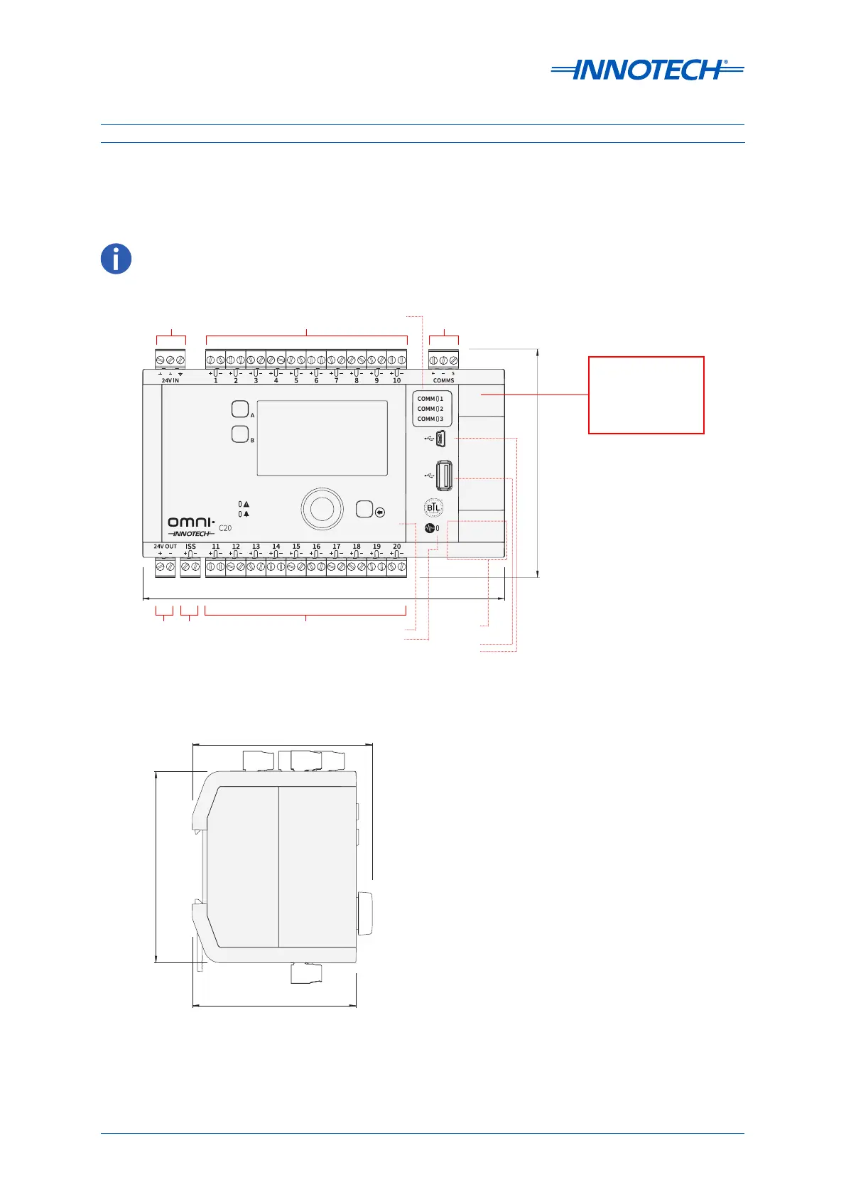
2-2.2 Omni C20 Controller Dimensions & Identification
The Omni C20 & C20D Controllers feature 20 programmable points, 3 RS-485 comms inputs, 2 RJ45
ethernet ports, USB A and Mini-B connections and an ISS RS-485 input.
87.90mm (3.46”)
93.40mm (3.68”)
80mm (3.15”)
Figure 2-7: Omni C20D Dimensions (End View)
Figure 2-6: Omni C20D Dimensions and Identification
180mm (7.09”)
113.44mm (4.47”)
Programmable
Points
24V
In
Comms
Input
Programmable
Points
ISS
Input
24V
Out
Ethernet
(on side)
USB A
USB Mini-B
The Expansion
Bay contains EOL
Jumpers, backup
Battery and
Expansion port.
Optional HMI
Heartbeat LED
Comms
Indicators
 Loading...


