Omni Installation Instructions
Page 36 © Mass Electronics Pty Ltd 2017Edition 1.2 dated 20.08.2018
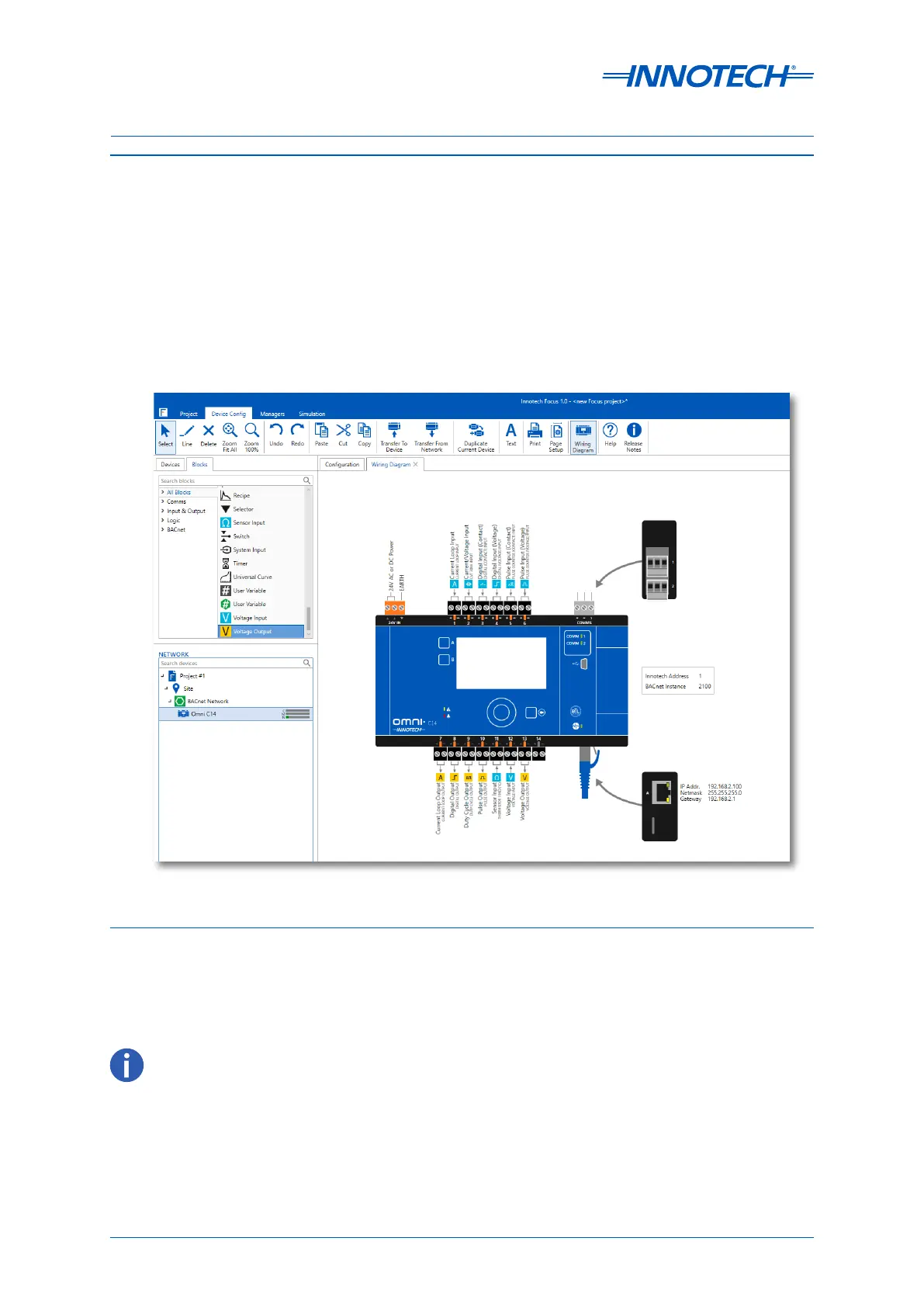
Below is an example of a typical computer-generated wiring diagram. A printout of the wiring
diagram and materials list is usually provided at the time of hardware delivery. Refer to Figure 3-1.
Figure 3-1: Focus Generated Wiring Diagram Example
3-4 Digital Controller Wiring
The following paragraphs contain input/output connection information for the Omni Controllers
and Omni devices. The Focus soware, which is used to configure and program the controller,
automatically produces a wiring diagram for the specific application. The wiring diagram and can be
easily printed and used for reference.
3-4.1 Common Programmable Point Information
Omni controllers are equipped with Programmable Points that can be configured using Innotech
Focus soware to suit a wide range of applications. Each Programmable Point has a signal terminal
(+) and a reference terminal (–) and can be configured as Inputs or Outputs.
See the Programmable Points specification table for more information.
 Loading...


