Page 25
Omni Installation Instructions
© Mass Electronics Pty Ltd 2017Chapter 2 – Mechanical Installation
2-2.4 Omni U10 Remote Expansion Module Dimensions & Identification
The Omni U10 can be used on the Omni C40 & C20 controllers. Each U10 adds an additional 10
Programmable Points to the connected Omni controller. The flexibility and features such as self-
diagnostics, individual LED status indication and the ability to program each point as an Input or
Output are all available as on the host controller.
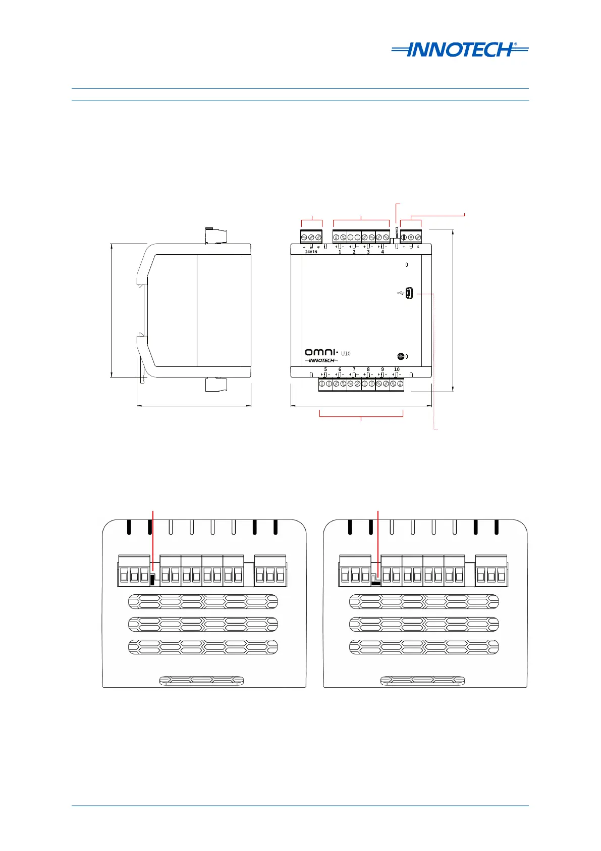
Figure 2-16: Omni U10 Dimensions and Identification
93.40mm (3.68”)
80mm (3.15”)
113.44mm (4.47”)
COMMS
COMMS
USB Mini-B
Programmable
Points
24V
In
Comms
Input
Programmable
Points
EOL
Jumper
Front ▶◀ Back
Figure 2-17: Omni U10 EOL Jumper Setting
EOL Jumper
Set Position
EOL Jumper Not
Set Position
 Loading...


