Page 41
Omni Installation Instructions
© Mass Electronics Pty Ltd 2017Chapter 3 – Electrical Installation
3-4.3.1 Power Input
The Omni C20 Controller power requirements are either AC or DC as below:
•24VAC ±20%, 50/60 Hz
•24VDC (18-35VDC)
•Power Consumption: 30 Watts max. (load dependent)
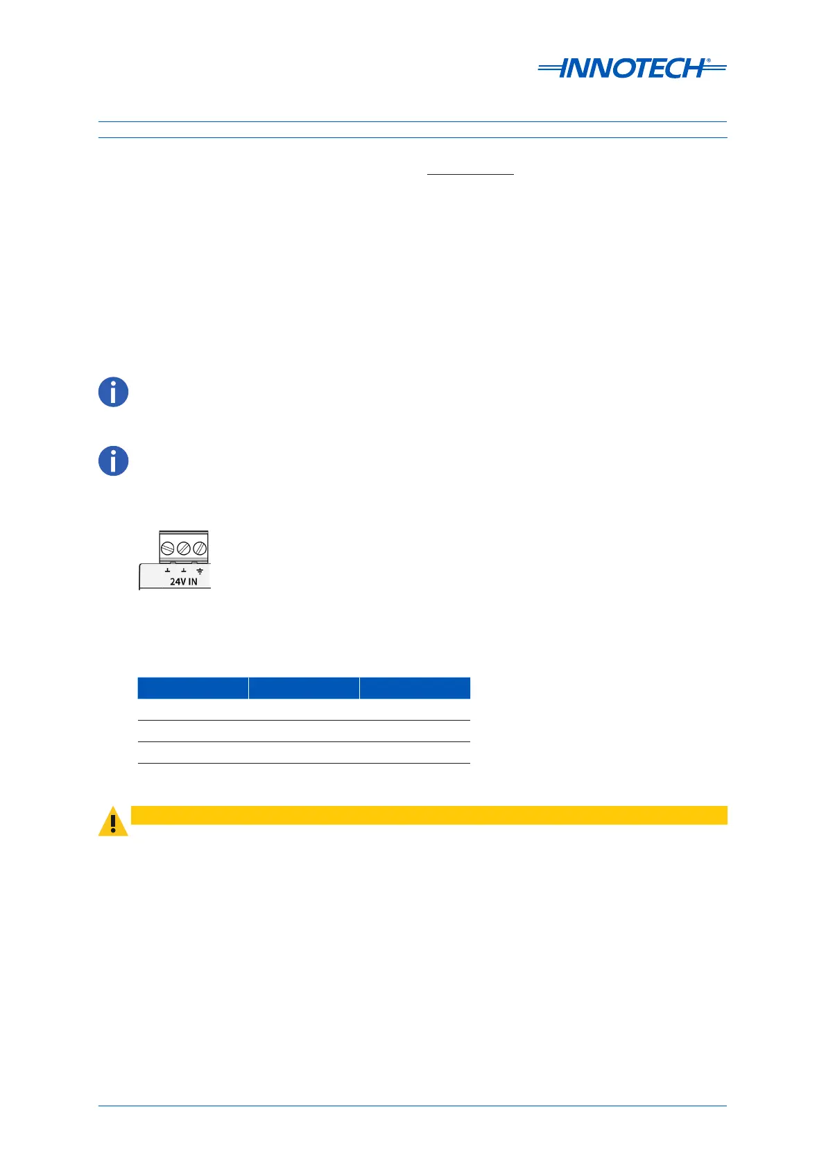
The Omni C20 has polarity independent supply wiring. The 24V and 0V wiring can be used in either
terminal 1 or 2 per the image below.
The operating voltage must meet the requirements of Safety Extra Low Voltage (SELV) to EN60730.
The transformer used must be a safety transformer in compliance with EN60742 and be designed for
100% duty. It must also be sized and fused in compliance with local safety regulations.
Figure 3-5: Omni C20/D 24V Input Terminals
1 32
The terminal numbering used in Figure 3-5 is only for identification purposes and does not relate to any numbering
on the physical controller.
Table 3-4: Recommended Wiring - C20
Terminal AC Supply DC Supply
1 24VAC 24VDC
2 0VAC (Neutral) 0VDC
3 Earth Earth
Terminal 3 as shown above in Figure 3-5 MUST be Earthed.
CAUTION
Terminals 1 & 2 in the image below are not polarity conscious, meaning EITHER terminal can be 24V or 0V. For the
purposes of clarity in this document, terminal 1 will be used for 24V and terminal 2 for 0V.
 Loading...


