Omni Installation Instructions
Page 40 © Mass Electronics Pty Ltd 2017Edition 1.2 dated 20.08.2018
3-4.3 Omni C20/D Controller
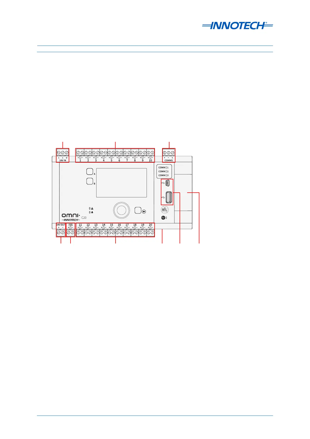
Figure 3-4 shows the input/output connection groups for the Omni C20 Controller. The controller uses
Phoenix type plug-in terminal strips located around the controller’s perimeter.
•Power Input (3-4.3.1)
•Programmable Points (UI/O) (3-4.3.2)
•24V Output (3-4.3.3)
•ISS Input (3-4.3.4)
•RS-485 Comms (3-4.3.5)
•Ethernet Communications Ports (3-4.3.6)
•USB Inputs (3-4.3.7)
Figure 3-4: Omni C20/D Input / Output Terminals
24V In Comms Inputs
24V
Out
ISS
Input
USB
Inputs
Expansion
Bay Cover
Ethernet
Input (on side)
Programmable Points
Programmable Points
 Loading...


