Omni Installation Instructions
Page 46 © Mass Electronics Pty Ltd 2017Edition 1.2 dated 20.08.2018
3-4.5 Omni U10 Remote Expansion Module
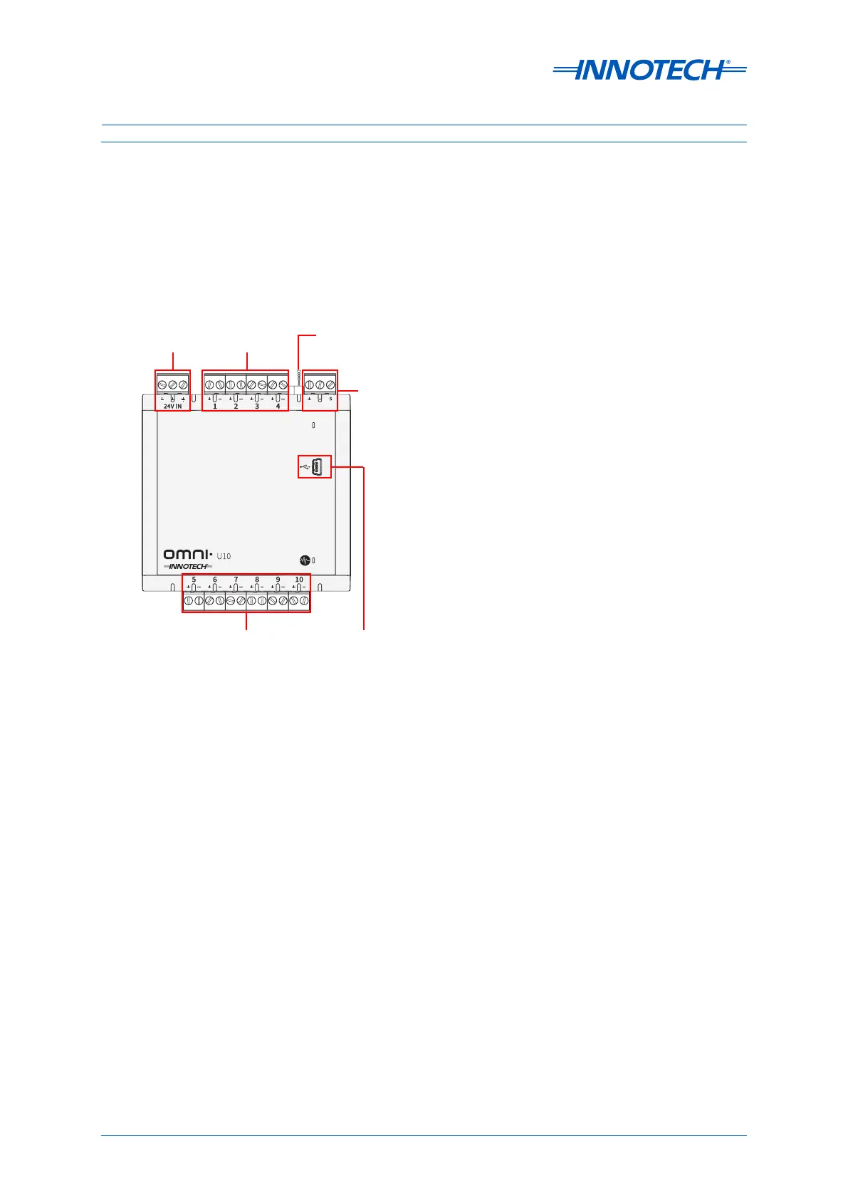
Figure 3-8 shows the input/output connection groups for the Omni U10 REM. The controller uses
Phoenix type plug-in terminal strips located around the controller’s perimeter.
•Power Input (3-4.5.1)
•RS-485 Comms (3-4.5.2)
•USB Port (3-4.5.3)
COMMS
COMMS
Figure 3-8: Omni U10 Input / Output Terminals
24V In
Comms
Input
USB
Input
EOL
Jumper
Programmable Points
Programmable
Points
 Loading...


