C40
C40
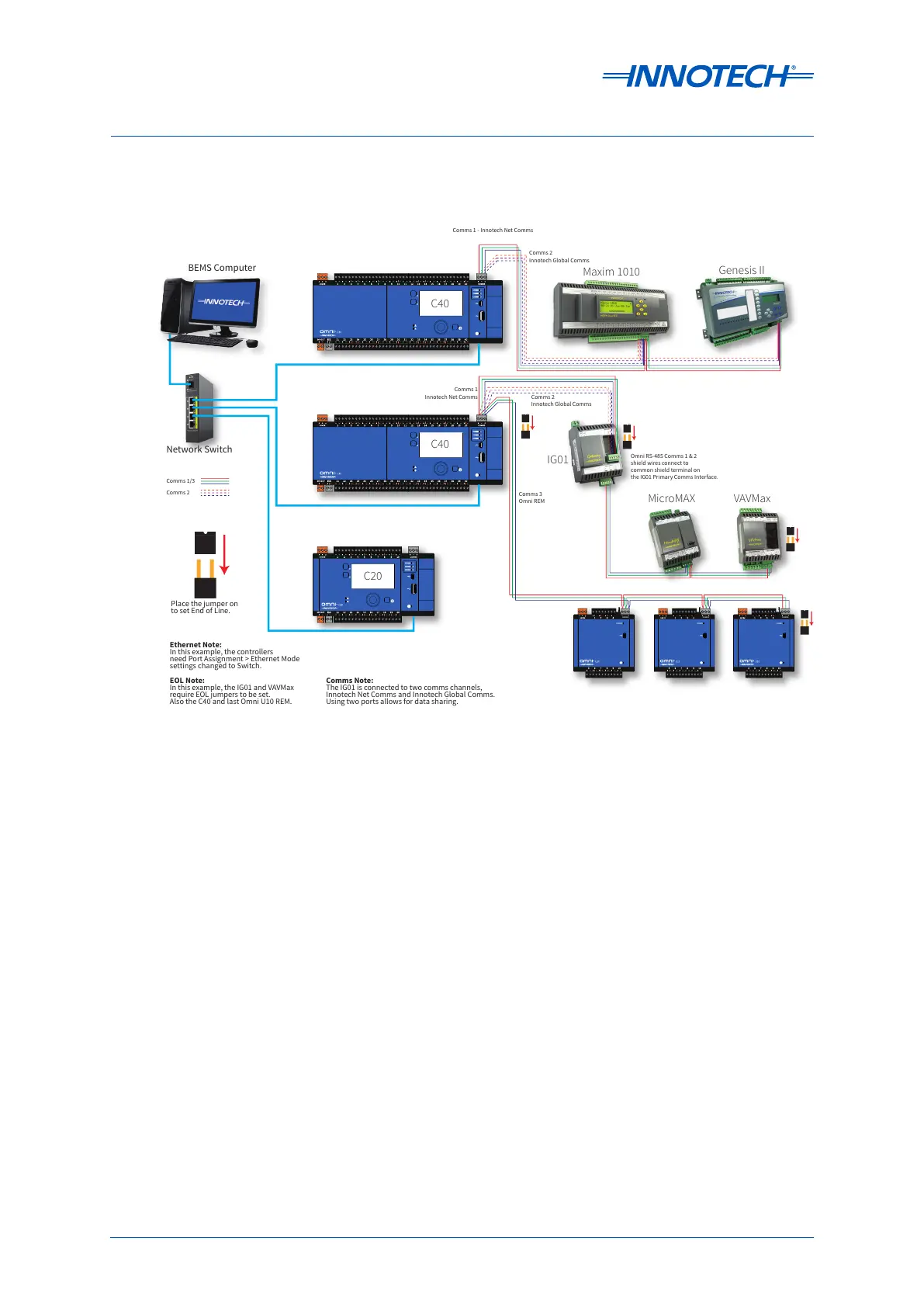
Place the jumper on
to set End of Line.
EOL Note:
In this example, the IG01 and VAVMax
require EOL jumpers to be set.
Also the C40 and last Omni U10 REM.
IG01
MicroMAX VAVMax
BEMS Computer
Network Switch
Ethernet Note:
In this example, the controllers
need Port Assignment > Ethernet Mode
settings changed to Switch.
COMMS
COMMS
COMMS
COMMS
COMMS
COMMS
Comms 1 - Innotech Net Comms
Maxim 1010
Genesis II
C20
Comms 2
Innotech Global Comms
Comms 2
Innotech Global Comms
Comms 3
Omni REM
Comms Note:
The IG01 is connected to two comms channels,
Innotech Net Comms and Innotech Global Comms.
Using two ports allows for data sharing.
Comms 1
Innotech Net Comms
Omni RS-485 Comms 1 & 2
shield wires connect to
common shield terminal on
the IG01 Primary Comms Interface.
Comms 1/3
Comms 2
 Loading...


