Appendix C
-
156
-
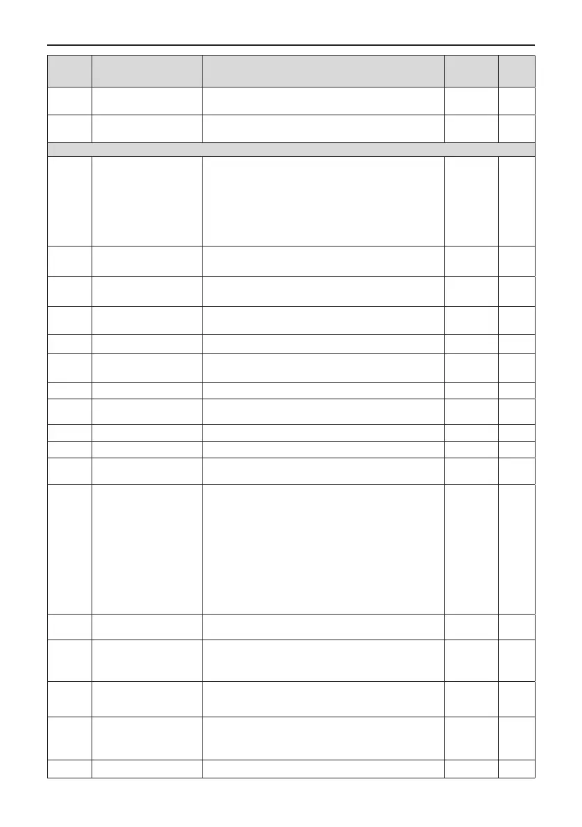
Function
Code
Name Setting Range Default Change
F2-22
Regenerative power limit
selection
0: Disabled
1: Enabled
0
☆
F2-23 Regenerative power limit 0.0% to 200.0%
Model
dependent
☆
Group F3: V/F Control Parameters
F3-00 V/F curve setting
0: Linear V/F
1: Multi-point V/F
2-9: Reserved
10: V/F complete separation
11: V/F half separation
Note: When F3-00 is set to 2 to 9, the actual linear V/F is
used.
0
★
F3-01 Torque boost
0.0%: No torque boost
0.1 to 30.0 %
Model
dependent
☆
F3-02
Cut-off frequency of
torque boost
0.00 Hz to max. frequency 50.00 Hz
★
F3-03
Multi-point V/F frequency
1
0.00 Hz to F3-05 0.00 Hz
★
F3-04 Multi-point V/F voltage 1 0.0% to 100.0% 0.0%
★
F3-05
Multi-point V/F frequency
2
F3-03 to F3-07 0.00 Hz
★
F3-06 Multi-point V/F voltage 2 0.0% to 100.0% 0.0%
★
F3-07
Multi-point V/F frequency
3
F3-05 to rated motor frequency F1-04, Hz 0.00 Hz
★
F3-08 Multi-point V/F voltage 3 0.0% to 100.0% 0.0%
★
F3-10 V/F over-excitation gain 0 to 200 64
☆
F3-11
V/F oscillation
suppression gain
0 to 100 40
☆
F3-13
Voltage source for V/F
separation
0: Set by F3-14
1: AI1
2: AI2
3: AI3
4: Pulse reference (DI5)
5: Multi-reference
6: Simple PLC
7: PID reference
8: Serial comms.
Note: 100.0% corresponds to the rated motor voltage
0
☆
F3-14
Digital setting of voltage
for V/F separation
0 V to rated motor voltage 0V
☆
F3-15
Voltage rise time of V/F
separation
0.0s to 1000.0s
Note: It is the time used for the voltage increases from 0 V
to the motor rated voltage.
0.0s
☆
F3-16
Voltage decline time of V/
F separation
0.0s to 1000.0s
Note: It is the time used for the voltage increases from 0 V
to the motor rated voltage.
0.0s
☆
F3-17
Stop mode selection for
V/F separation
0: Frequency and voltage declining to 0 independently
1: Frequency declining after voltage declines to 0
0
☆
F3-18 Current limit level 50% to 200% 150%
★

 Loading...