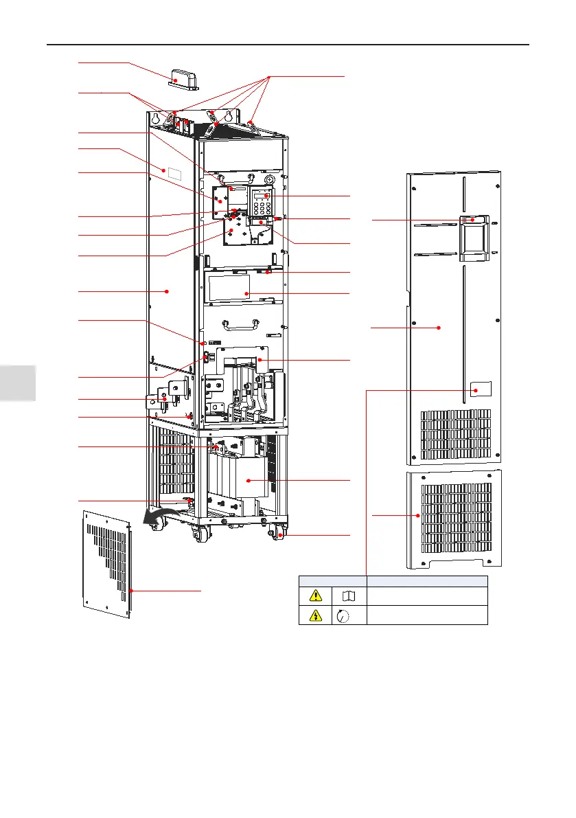
Top hoist rings
Protective cover of DC bus terminals
DC bus terminals
Fixing pin of extension
encoder card
Main circuit input
terminals
Bottom hoist hole
Housing
Warning
label
LOGO
Castor
Fan box
For replacement of fan,
see section 7.3
Cable clamp
Control circuit
terminals
See section
3.2.4
Main circuit output
terminal
See section 3.2.2
Grounding terminal
See section
3.
2.2
Output AC Reactor
Front lower
cover
Live indicator
Do not remove/install the drive
when this indicator is lighting
EMC and VDR screw
Refer to Power Grid
System in section 3.2.
2
Ground bar
Ground the PG card and
control board
Fixing pin of extension card
See Appendix A Optional Cards
Operating panel
See section 4.
2
Cabling tray and fixing
pin of ground cable of
control board
This ground cable can only
be connected to the ground
bar after the system is
grounded reliably.
Interface of external
operating panel
See section 4.3
Barcode
View the serial number and
model of the drive here.
Nameplate
Front upper
cover
For replacement
,
see 3.1.5
Description
i
10min
DANGER! Do not remove the front cover while the
power is on or within10 minutes after the power is
turned off.
CAUTION! Read the user guide of the AC drive carefully
before installation or operation.
Warning label
Left side board of base
Label of main
circuit wiring

 Loading...