3 Installation and Wiring
-
42
-
3
4. DC bus terminals (+) and (-)
●
DC bus terminals, labeled (+) and (-), are terminals that carry a residual voltage for a period after the drive
has been switched off.
●
To avoid risk of equipment damage or re, when you select an external braking unit for use with an AC drive
of 90 kW and above, DO NOT reverse the poles (+) and (–).
●
Use a cable not exceeding 10 m to connect DC bus terminals to the external MDBUN braking unit. Use
twisted pair wires or close pair wires for this connection.
●
Fire risk! Do not connect the braking resistor directly to the DC bus.
5. Braking Resistors (+) and BR
●
Braking resistor terminals (+) and PB are only for the drive units up to 75 kW that are tted with an internal
braking unit.
●
To avoid risk of equipment damage, use a cable not exceeding 5 m to connect an external braking resistor.
●
To avoid risk of ignition due to overheating of the braking resistor, do not place anything combustible around
the braking resistor.
●
Set F6-15 (Braking use ratio) and F9-08 (Braking unit action initial voltage) correctly according to load after
connecting the braking resistor to the drive of up to 75 kW that is tted with an internal braking unit.
6. AC Drive Outputs UVW
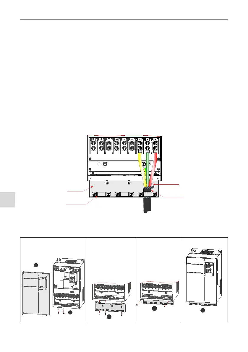
Grounding clamp
for screen/shield
Main circuit cables
Cable support
bracket (optional
)
Use heatsink tube
or insulation tape
to terminate the
screen/shield
Screen/shield
Figure 3-33 Drain wire
The cable support bracket in Figure 3-33 is an optional accessory. You need to buy a bracket applicable to
MD500T160G and previous models. Installation of the bracket is shown below.
(
1) Remove the cover.
(2)
Unscrew two M4*12 screws on
the inlet plate.
(
3) Install the cable
support bracket to
the drive, and secure
it to the position 3
with three M4*12
screws.
(
4) Secure the two
positions with two
M4*12 screws.
(
5) Ret the cover.
Figure 3-34 Installation of cable support bracket

 Loading...