3 Installation and Wiring
-
43
-
3
Table 3-5 Cable support bracket models
Cable Support Bracket Model Applicable AC Drive Model
MD500-AZJ-A2T1
MD500T0.4GB
MD500T0.7GB
MD500T1.1GB
MD500T1.5GB
MD500T2.2GB
MD500T3.0GB
MD500-AZJ-A2T2
MD500T3.7GB
MD500T5.5GB
MD500-AZJ-A2T3
MD500T7.5GB
MD500T11GB
MD500-AZJ-A2T4 MD500T15GB
MD500-AZJ-A2T5
MD500T18.5G(B)(-T)
MD500T22G(B)(-T)
MD500-AZJ-A2T6
MD500T30G(B)
MD500T37G(B)
MD500-AZJ-A2T7
MD500T45G(B)
MD500T55G(B)
MD500-AZJ-A2T8
MD500T75G(B)
MD500T90G
MD500T110G
MD500-AZJ-A2T9
MD500T132G
MD500T160G
●
Cable specication and installation of all cables connected to the drive output U, V, W must comply with
local safety regulations and relevant IEC standards.
●
Refer to Table 8-7 Peripherals and options for recommendations and copper conductor dimensions of ca-
bles in the main circuit.
●
To avoid risk of equipment damage or operating faults, do not connect a capacitor or surge absorber to the
output side of the AC drive.
●
Long motor cables can contribute to electrical resonance caused by distributed capacitance and induc-
tance. In some cases, this might cause equipment damage in the drive, in motor or in cables. To avoid
these problems, install an AC output reactor close to the drive if cable is longer than 100 m.
●
The shielding cables are recommended for the motor. The shielding layer must be wound onto the cable
support bracket. The drain wire must be grounded to the grounding (PE) terminal.
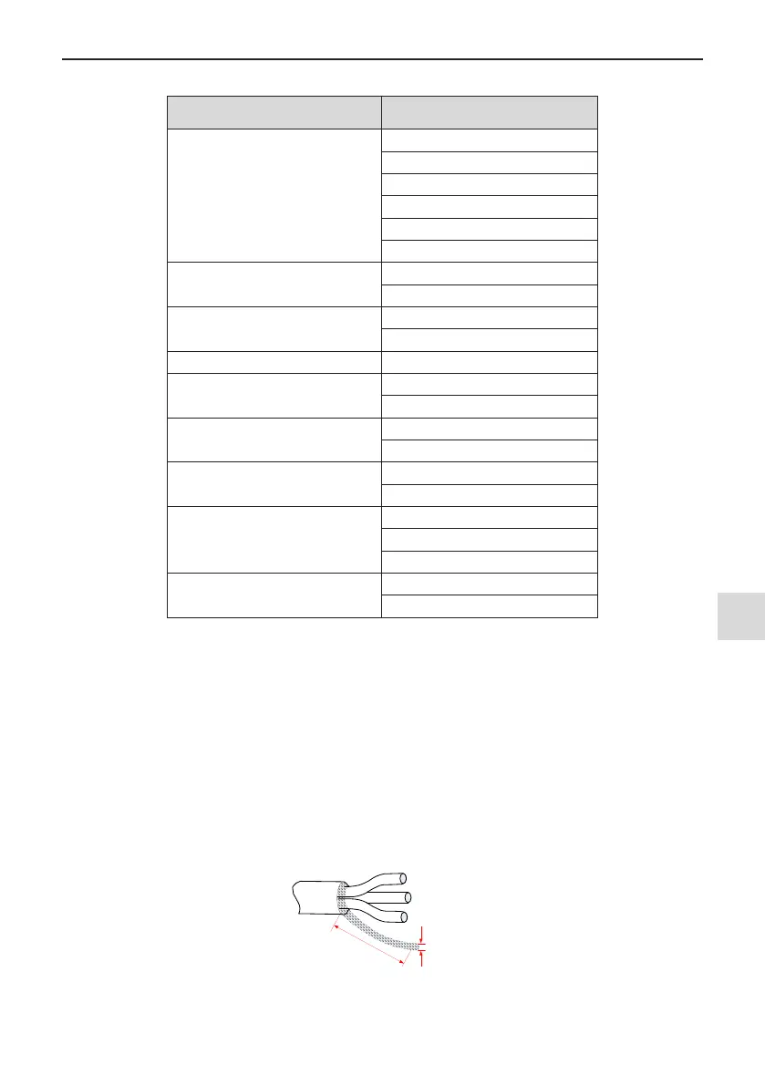
●
Ensure the drain wire of the motor cable shield is as short as possible and its width must be no less than
1/5 of its length.
Figure 3-35 Drain wire of motor cable shield

 Loading...